The following logic tables come from Axia consoles. Axia consoles have profiles for sources which define many things and one of those properties are GPIO controls. Each table is titled by the source profile type. The functionality is fixed and if the GPIO port is configured to the source number, the GPIO port will participate in the defined logic that is created by the console logic in those other products.
Operator and Control Room Producer Microphone
Designator | Name | Pin | Description |
INPUTS |
IN-1 | ON command | 11 | Turns channel ON |
IN-2 | OFF command | 12 | Turns channel OFF |
IN-3 | TALK1 command (to Studio) | 13 | Routes Mic audio to talkback mix and inserts mix into the Studio 2 monitor mix |
IN-4 | MUTE command | 14 | Mutes channel |
IN-5 | TALK2 command (to sources in Preview or IFB) | 15 | Routes Mic audio to talkback mix and inserts mix into any backfeed source that is engaged in Preview (IFB) |
OUTPUTS |
OUT-1 | ON lamp | 1 | Active when the channel is ON unless TALK or MUTE are active. |
OUT-2 | OFF lamp | 2 | Active when the channel is OFF. |
OUT-3 | TALK1 lamp | 3 | Active when TALK to Studio is engaged |
OUT-4 | MUTE lamp | 4 | Active when MUTE is engaged |
OUT-5 | TALK2 lamp | 5 | Active when TALK to Previewed sources is engaged |
Guest Microphone (Control Room or Studio)
Designator | Name | Pin | Description |
INPUTS |
IN-1 | ON command | 11 | Turns channel ON |
IN-2 | OFF command | 12 | Turns channel OFF |
IN-3 | TALK command (to CR) | 13 | Mutes channel and routes Mic audio to Preview mix |
IN-4 | MUTE command | 14 | Mutes channel |
IN-5 |
| 15 | No logic associated with type |
OUTPUTS |
OUT-1 | ON lamp | 1 | Active when the channel is ON unless TALK or MUTE are active. |
OUT-2 | OFF lamp | 2 | Active when the channel is OFF. |
OUT-3 | TALK lamp | 3 | Active when TALK is engaged |
OUT-4 | MUTE lamp | 4 | Active when MUTE is engaged |
OUT-5 |
| 5 | No logic associated with type |
Line
Designator | Name | Pin | Description |
INPUTS |
IN-1 | ON command | 11 | Turns channel ON |
IN-2 | OFF command | 12 | Turns channel OFF |
IN-3 | Preview command | 13 | Turns the channel’s Preview (IFB) ON |
IN-4 | RESET command | 14 | Turns channel OFF while not triggering STOP pulse |
IN-5 | READY command | 15 | Enables the OFF button to be illuminated if “GPIO ready” feature is enabled in source profile |
OUTPUTS |
OUT-1 | ON lamp | 1 | Active when the channel is ON |
OUT-2 | OFF lamp | 2 | Active when the channel is OFF and READY (if enabled) |
OUT-3 | PREVIEW lamp | 3 | Active when PREVIEW (IFB) is engaged |
OUT-4 | Start pulse | 4 | 100 msec pulse when the channel status changes from OFF to ON |
OUT-5 | STOP pulse | 5 | 100 msec pulse when the channel status changes from ON to OFF |
Codec
Designator | Name | Pin | Description |
INPUTS |
IN-1 | ON command | 11 | Turns channel ON |
IN-2 | OFF command | 12 | Turns channel OFF |
IN-3 | TALK1 command (to CR) | 13 | Mutes channel and routes audio to Preview mix |
IN-4 | MUTE command | 14 | Mutes channel |
IN-5 | TALK2 command (to SOURCE) | 15 | Triggers the TALK TO SOURCE function routing Operator Mic to codec |
OUTPUTS |
OUT-1 | ON lamp | 1 | Active when the channel is ON unless TALK or MUTE are active. |
OUT-2 | OFF lamp | 2 | Active when the channel is OFF. |
OUT-3 | TALK1 lamp | 3 | Active when TALK to control room is engaged |
OUT-4 | MUTE lamp | 4 | Active when MUTE is engaged |
OUT-5 | TALK2 lamp | 5 | Active when TALK TO SOURCE is active |
Telephone
Designator | Name | Pin | Description |
INPUTS |
IN-1 | ON command | 11 | Turns channel ON |
IN-2 | OFF command | 12 | Turns channel OFF |
IN-3 | Preview command | 13 | Turns the channel’s Preview (IFB) ON |
IN-4 | RESET command | 14 | Turns channel OFF while not triggering STOP pulse |
IN-5 | READY command | 15 | Enables the OFF button to be illuminated if “GPIO ready” feature is enabled in source profile |
OUTPUTS |
OUT-1 | ON lamp | 1 | Active when the channel is ON |
OUT-2 | OFF lamp | 2 | Active when the channel is OFF and READY (if enabled) |
OUT-3 | PREVIEW lamp | 3 | Active when PREVIEW (IFB) is engaged |
OUT-4 | Start pulse | 4 | 100 msec pulse when the channel is first turned ON or PREVIEW (IFB) is selected. |
OUT-5 | STOP pulse | 5 | 100 msec pulse when the channel is turned OFF or PREVIEW (IFB) is disengaged. |
Computer Playout
Designator | Name | Pin | Description |
INPUTS |
IN-1 | ON command | 11 | Turns channel ON |
IN-2 | OFF command | 12 | Turns channel OFF |
IN-3 | Preview command | 13 | Turns the channel’s Preview (IFB) ON |
IN-4 |
| 14 | No logic associated with type |
IN-5 | READY command | 15 | Enables the OFF button to be illuminated if “GPIO ready” feature is enabled in source profile |
OUTPUTS |
OUT-1 | Next Pulse | 1 | 100 msec pulse when the ON button is pressed |
OUT-2 | OFF lamp | 2 | Active when the channel is OFF and READY (if enabled) |
OUT-3 | PREVIEW lamp | 3 | Active when PREVIEW (IFB) is engaged |
OUT-4 | Start pulse | 4 | 100 msec pulse when the channel status changes from OFF to ON |
OUT-5 | STOP pulse | 5 | 100 msec pulse when the channel status changes from ON to OFF |
Monitors (Control Room)
Designator | Name | Pin | Description |
INPUTS |
IN-1 | MUTE Command | 11 | Mutes monitors and preview |
IN-2 | DIM Command | 12 | Dimming is applied to monitor |
IN-3 | EXT PREVIEW command | 13 | Routes external preview defined source into PREVIEW |
IN-4 | TALK TO EXTERNAL command | 14 | Enables TALK TO EXTERNAL where Operator Mic is routed to the Talk to External output |
IN-5 |
| 15 | No logic associated with type |
OUTPUTS |
OUT-1 | ON AIR lamp | 1 | Active when the Monitor is muted |
OUT-2 | DIM lamp | 2 | Active when the Monitor is DIMMED |
OUT-3 | PREVIEW lamp | 3 | Active when PREVIEW (IFB) is engaged |
OUT-4 | TALK TO EXT lamp | 4 | Active when TALK TO EXT is engaged |
OUT-5 | Talk to CR | 5 | Active when a source is active in talking to Control Room |
Monitors (Studio)
Designator | Name | Pin | Description |
INPUTS |
IN-1 | MUTE Command | 11 | Mutes monitors |
IN-2 | DIM Command | 12 | Dimming is applied to monitor |
IN-3 | Trigger timer | 13 | Resets Count-up timer |
IN-4 | Tigger countdown timer | 14 | Resets Count-down timer |
IN-5 |
| 15 | No logic associated with type |
OUTPUTS |
OUT-1 | ON AIR lamp | 1 | Active when the Monitor is muted |
OUT-2 | DIM lamp | 2 | Active when the Monitor is DIMMED |
OUT-3 | Timer trigger lamp | 3 | 100ms pulse when timer is started |
OUT-4 | Countdown trigger lamp | 4 | 100ms pulse when countdown timer is started |
OUT-5 | TALK TO STUDIO lamp | 5 | Active when TALK TO STUDIO is active |
The connector pinout for the DA15 is composed of 5 inputs, a common return, 5 outputs, an in common, a 5 volt DC source, and a source ground.

The maximum allowed external power supply for logic is 48 volts DC. The use of current limiting resistor is required for some voltages.
INPUT |
|
VDC | External Series Resistor |
5 | 0 |
6 | 0 |
12 | 680 @ ¼ watt |
24 | 1.8k @ ½ watt |
48 | 3.9k @ 1 watt |
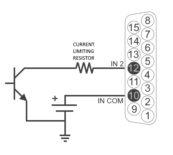
A sample circuit if using an external supply.

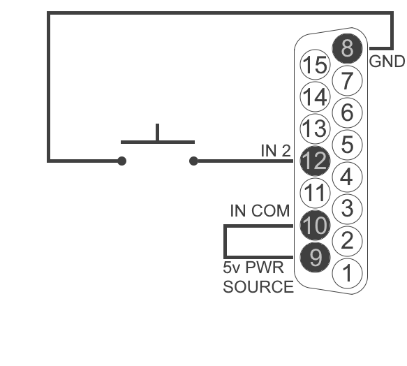
Take note to use current limiting resistor per the previous chart if the voltage supplied is above 6vDC. The intention is to limit the current to 20mA for each GPI pin. If the equipment being connected is electrically isolated, then the use of the GPIO port’s power supply is acceptable.

Axia GPIO accessory modules are designed to interface directly to the GPIO port. The DA15 connector on the back of an accessory module is a direct pin-to-pin match to the GPIO port of the xNode2. Premade cables of this configuration are commonly available through companies that specialize in interconnect cable assembly products.
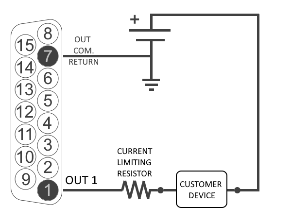
The GPO pins are solid state relays. Current should be limited to a combined 100mA through all the pins of a port. A connection with an external power supply would appear as follows.

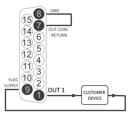
If the device being connected is electrically isolated, than the 5vDC supply can be used, maintaining a 100mA limit on current drawn.

The Axia accessory modules use the 5vDC supply to illuminate LED based buttons. So a one-to-one pin connection is all that is needed between any accessory modules and a GPIO port.
All the inputs and outputs on a specific GPIO port are “grouped together”. The 5 outputs are on 5 separate output pins, however, they share the same Common Return connection on pin-7. Similarly, the 5 inputs pins would be pulled to ground to activate them, and they share a common pin for a high-side rail on pin-10. If more than one connected device is to be connected to a single 15 pin port , you must make sure that the two units in question have the same ground potential or ground loops will occur. It is recommended that only one remote device be connected to each port to assure complete electrical isolation.
