Pathfinder Core PRO's event system is called Logic Flows. It shows your logic visually so that you can see how things work within your system.
Click Automation > Logic Flows in the navigation bar to open the Logic Flows user interface.
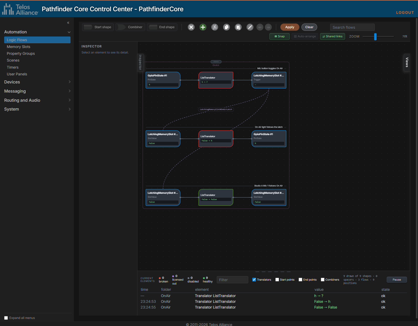
Each Logic Flow can be thought of as an event. More specifically, a Logic Flow is a set of property translations. During an event, we convert an input property value to an output property value.
You design a Logic Flow from four components:
Name | Description |
|---|---|
Start Point | A property in the system being monitored for changes. |
End Point | A property in the system which will be changed by the Logic Flow. |
Translator | A list of changes that can be applied to the value of a property. |
Combiner | A way to logically combine multiple states using logical operators such as AND, OR, and NOT. |
Using these tools, you can visually build Logic Flows to accomplish almost any task.
The Logic Flows Editor
The editor has five areas:
Area | Where | What it is for |
|---|---|---|
Toolbar | Top | Adding and editing flows, Apply and Clear, search, and the canvas controls. See Toolbar Controls. |
Inspector | Left | Details of whatever is selected on the canvas. Click the Inspector tab on its edge to show or hide it. |
Canvas | Center | The flows in the selected Views, drawn as cards joined by wires. |
Views | Right | The folders that organize your flows. Click the Views tab on its edge to show or hide it, and drag its left edge to change its width. |
Live activity | Bottom | A running list of values passing through the flows on screen. Drag the grip on its top edge to make it taller, up to half the window. |
The editor remembers the zoom level and the size of each pane in your browser.
Organizing Logic Flows with Views
When you first look at the Logic Flows screen, you will see an organizational panel on the right called Views. Think of Views as folders in your computer's file system: containers into which you can place Flows, so you can keep all Flows related to a certain subject in the same place.
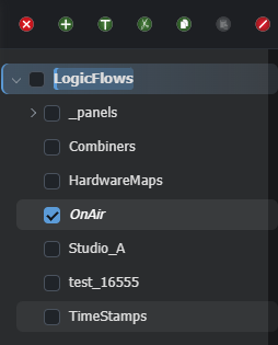
Creating a New View
To create a new View:
Check an existing View (this will become the parent View).
Click the Add (plus) button in the Views panel.
Type a Name for the new View and click Add.
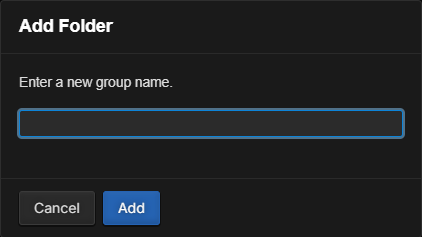
Spaces in a View name are shown as underscores in the Views tree.
As with folders on your computer, you can nest Views as deeply as you like. While you can add Flows to the master LogicFlows View (your “Root” folder), this is not recommended because LogicFlows is the one View that you cannot completely delete. Instead, devise a View naming strategy and create additional Views underneath LogicFlows to store your Flows.
There are two special Views called HardwareMaps and _panels. These Views are created by the system and used to manage the mapping of software buttons to hardware controls and bindings in HTML5 user panels. The chapter on HTML5 panels describes them. The system manages these Views, so do not delete them.
Manipulating Existing Views
With a View selected:
Icon | Function | Description |
|---|---|---|
X | Delete | The system asks for confirmation. Deleting a View also deletes all of its Logic Flows and descendant Views. |
+ | Add | Adds a new View inside it. |
T | Rename | Click this icon to rename the selected View. |
Scissors | Cut | With a single View selected, click this icon to move the selected View to the clipboard. |
Pages | Copy | With a single View selected (see note below), click this icon to copy the selected View to the clipboard. |
Clipboard | Paste | After pasting a cut View back into the system, the original View is deleted. When pasting a copied View back into the system, you will be prompted to give the pasted View a new name. |
Slash | State Toggle | Click this button to toggle all Logic Flows in the selected Views between the Enabled and Disabled states. If the recursion checkbox is checked, this also enables or disables flows in sub-Views. |
Important Note: You cannot select multiple Views for copy and paste operations, though if you select a View with child Views, those child Views are included in the copy operation. All pasted Logic Flows will be in a disabled state whether the operation started as a cut or a copy. Each flow keeps its own settings, such as Raise Output, Skip startup state, execution limit, recursion detection and Use FIFO.
The system assumes that after a copy and paste, you will want to modify the Start and End Points of the Flow to reproduce behavior using different End Points.
View cut, copy, and paste operations are completed by the Pathfinder Core PRO appliance rather than by the browser, so they do not require an Apply.
Under the hood, the browser sets a write-only CopyTo property on the copied View folder object via a SapV2 Set message. The value used in the set message is the path to which the View should be copied. The Pathfinder Core PRO Logic Flow engine then handles the data cloning.
Moving a Flow to Another View
Drag a flow and drop it on a View in the Views tree to move it there. While you drag, a + New folder… row appears at the bottom of the tree; drop the flow on it to create a new View and move the flow into it in one step.
Toolbar Controls

From left to right, the Toolbar controls are:
Control | Description |
|---|---|
Start shape | Allows you to add a Start Point and a Translator to the left side of a Combiner or to extend the Flow’s start to a new Flow. |
Combiner | Allows you to add a Combiner. |
End shape | Allows you to add an End Point and a Translator to the right side of a Combiner or to extend the Flow’s end into a new Flow. |
Delete (X) | Allows you to delete a Flow, Flow Combiner, or Translator. |
Add flow (+) | Creates a new Flow. |
Cut | Cuts a Flow to the clipboard. |
Copy | Copies a Flow to the clipboard. |
Paste | Pastes a Flow from the clipboard. |
Disable (slash) | Disables or enables a Flow, Combiner, or Translator. |
Undo, Redo (arrows) | Step back and forward through your edits since the last Apply, including moves. |
Apply Button | Applies pending changes to the system. |
Clear Button | Clears pending changes and reverts to the system’s actual state. |
Search flows | Highlights the flows that contain the text you type, with a count of matches. |
Snap | When on, cards you drag snap to the grid. |
Auto-arrange | Discards the positions you have dragged cards to and returns to the automatic arrangement. |
Shared links | When on, draws links between flows that write and read the same object. See Shared Links. |
Zoom | Sets the zoom from 25% to 400%. |
Each Toolbar control is enabled only when it can currently be used. For example, the Cut icon is not enabled unless you have selected a Flow that can be cut.
While you have changes that have not been applied, Apply is highlighted and ● Unsaved changes is shown beside it:

Working on the Canvas
Cards
Each part of a flow is drawn as a card:
Start and End Points show the object and its number, the property, and the property's current value. A point that has not been chosen yet shows Not set.
Translators show the value that last went through them, as input → output.
Combiners are drawn as shapes: logic gates for AND, OR, NOT and the other logical types, an oval for EQUALITY, a diamond for PASSTHRU, a circle for DELAY, and a relay symbol for RELAY. Each shows its current inputs and output.
A translator's color shows which entry of its translation list matched most recently, so you can see which rule fired without opening it. Red means the current input and output match no entry. These colors come from a file that you can edit on an advanced web page if necessary.
Disabled elements are drawn grayed out. The counters at the top of the Live activity console show how many elements on screen are broken, licensed out, disabled and healthy:
Broken: the element could not be found in the system.
Licensed out: the element is beyond what the current license allows, so it does not run.
Disabled: the element, or its flow, has been disabled.
Selecting and Moving
Click a card to select it; its details appear in the Inspector.
Click a flow's empty space to select the whole flow.
Drag a card to move it. With Snap on, it snaps to the grid. Hold Alt while dragging a card to move its whole flow.
Drag across empty canvas to select several cards. Hold Ctrl to add to the selection. Selected cards move together.
Double-click a card to edit it.
Positions you drag cards to are saved in Pathfinder Core PRO, so everyone sees the same layout. Auto-arrange discards them. Views you open for the first time are arranged automatically, and positions are never saved for the system Views _panels and HardwareMaps.
Zooming
Use the Zoom slider, or hold Ctrl and turn the mouse wheel. Double-clicking empty canvas zooms to 75% around the point you clicked.
First Flow
These tools are easier to understand if we walk through creating a Flow.
Click the LogicFlows checkbox, then click the Plus icon in the Views panel.
Type a name for the new View and click Add.
You can select several Views to see their Flows together on the same screen, but to create a new Flow you must select a single View so the system knows where to place it. Click the new View’s checkbox to select it, then click the root LogicFlows View to uncheck its checkbox so only your new View is selected.
Once a single View is selected, the Add flow button (plus) in the main control panel for Logic Flows is enabled. Click the Add flow button to create a new Flow consisting of a Start Point, a Translator, and an End Point:

Important Note: These are pending changes that have not been submitted to the system yet. So far, they exist only in your browser.
All Flows must have at least one Start Point, one Translator, and one End Point, which is the simplest Flow you can create. However, we have not yet set parameters to define what this Flow will do. You can define the options for each block in this Flow by double-clicking the block, though double-clicking the Translator itself does nothing until the Start Point and End Point are defined. The reason for this will be explained shortly.
Double-click the Start Point block to open the property selector dialog. Use this dialog to select the property that the new Flow will monitor for changes.
Use the arrows to expand and navigate into the objects in the system until you find the object and property you want to select. Properties have a green dot next to them instead of an expansion arrow.
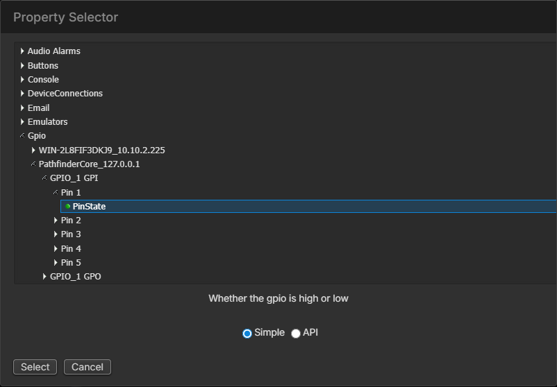
You can either click the property you want to monitor and then click Select, or just double-click the property to select it.
In this example, we are selecting the PinState property of GPI#1, Pin#1 on Pathfinder Core PRO's own GPIO node. Notice that as you select properties in this dialog, a description of the property usually appears underneath the tree window, providing more detail about the property’s purpose.
Important Note: The property selector dialog has a simple list and an API list. The API list is recommended only for advanced users, so it is not discussed until later in the documentation.
Important Note: Hover over a Start Point that has been assigned a property to see a pop-up box with more detail about that property.
Double-click the End Point block and repeat the procedure to select the End Point or property we want this Flow to change. In this example, we pick GPO#1, Pin#1 to make the GPO state follow the GPI state.
At this point, the Flow looks something like:
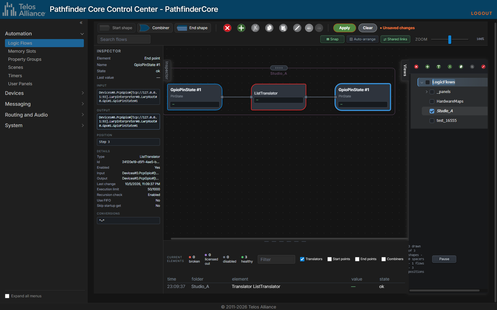
Important Note: The list of available properties differs depending on whether you are editing a Start Point or an End Point. This is because the system knows whether a property is read only, read write, or write only. Properties that are read only may not be used as an End Point (something you want to change). The system will only display properties that make sense for the type of block you are editing.
With the Start and End Points configured, you can edit the translation table by double-clicking the ListTranslator block.
In the dialog that opens, enter the list of translations you want to execute as part of this Logic Flow. The other buttons on the translation list screen can be used to move translation definitions up and down in the list, insert new ones, and remove them.
Select the top translation point (*=*) to enable the drop-down boxes below. The left drop-down has Low and High as options, and the right drop-down has a list of GPO states. For this example, select Low in the left drop-down and Low in the right drop-down:
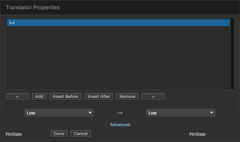
Click Add to add another translation to the list. For this example, select High in the left drop-down and High in the right drop-down:
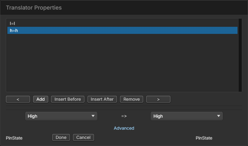
You cannot edit the translation block until the Start and End Point properties are configured because the system filters the list of possible options depending on the property selected. For example, in this case, Low and High were available options on the left, and GPO states were available on the right. If the End Point had been the CurrentSourcePath property of a destination, the right drop-down would present a list of available router sources.
We have just defined that if the Start Point (GPI) is Low, the GPO is set to Low. If the GPI is High, the GPO is set to High. In effect, we are defining a list of rules for what the End Point value should be depending on the Start Point property value.
When creating translation items, the asterisk serves as a special wildcard that will be evaluated as “any” value. For example, we could have made the second entry in this translation list *=High.
Since the list is analyzed in order, this would mean that if the GPI is Low, then the GPO should be set Low. If the GPI is anything other than Low, then the GPO should be set High. In this case, using * and explicitly defining High are equivalent because the GPI only has two possible states.
The * is useful when there are multiple options on the Start Point side. For example, if the Start Point were the current source routed to a destination, we could build the translation such that if a specific source is selected the indicator would be On, and then use the * to say if there is any other source routed, turn it Off.
Order is important. If you were to move *=Off to the top of the list, the indicator would always be Off because the first item in the list says if anything, then Off, and the system would never analyze any of the other items in the list.
A * should almost always appear at the end of a list of translations as a catchall. A * on the right-hand side of the translation means to pass the value from the left on unchanged. So *=* would pass anything from the Start Point to the End Point (or next step in the Flow) unchanged.
If you are familiar with programming languages, this list works much like a select case or switch statement. When the Start Point property changes, the value is analyzed in order through this list until a match is found, and then the correct value is applied to the End Point or next step in the Flow. If no match is found, the End Point is not changed.
Once you are finished, click Done.
This Flow is not active yet. In the top toolbar, the highlighted Apply button indicates changes are pending. Click Apply to commit the changes to Pathfinder Core PRO.
The Flow now changes color to show that it is live and active:
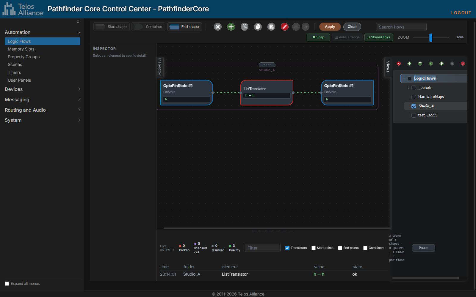
Important Note: Hover over the translator to see the GUID that identifies it at the bottom of the hover balloon. This makes it easier to match the graphical element to the API and backup files.
Dynamic Data
The Flow diagram does not simply show the design of the Logic Flows in your system. It also shows the live, up-to-the-second state of each of the Flows. Each Start and End Point shows its property's current value, each translator shows the last input → output it carried out, and each combiner shows its inputs and output. A translator's color shows which rule matched, and red means the current value matched no rule. These live changes make monitoring and troubleshooting much easier.
The Inspector
Click any card to see its details in the Inspector. For a translator these include its state, last value, input and output paths, its position in the flow, its ID, when it last changed, its execution limit, recursion detection, Use FIFO and Skip startup settings, and its translation list. Click Edit translations… to open the translation list, or click the Input or Output path to open the Property Selector.
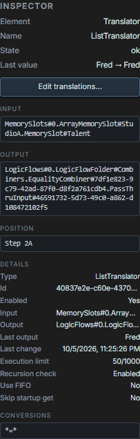
The ID in the Inspector identifies the translator in the API and in backup files.
Live Activity
The Live activity console at the bottom of the editor lists the values passing through the flows on screen, newest first, with the time, View, element, value and state.

Type in Filter to show only matching rows.
Check Translators, Start points, End points and Combiners to choose what is listed. Translators are listed by default.
Click Pause to stop the list scrolling while you read it.
Click a row to find that element on the canvas.
Searching
Type in Search flows on the toolbar to highlight every flow that contains the text, such as a memory slot or device name. The number of matches is shown beside the box.
Adding Combiners
Translation points are one-to-one only. In other words, we are translating one value from a property to another value on another property. Combiners, on the other hand, allow us to pass values to multiple End Points and make logical decisions based on more than one Start Point.
To add a Combiner, click a Translator in an existing Flow to enable the Combiner tool in the toolbar, then click the tool to insert a Combiner into the Flow.
With the Flow we created in the example above, the result looks like this:

Combiners can perform many useful functions, but each Combiner type requires a minimum number of inputs and is limited to a maximum number of inputs.
Type | Minimum Inputs | Maximum Inputs |
|---|---|---|
AND | 2 | Any |
OR | 2 | Any |
NAND | 2 | Any |
NOR | 2 | Any |
XOR | 2 | Any |
XNOR | 2 | Any |
NOT | 1 | 1 |
RELAY | 2 | 2 |
PASSTHRU | 1 | 1 |
EQUALITY | 2 | Any |
DELAY | 1 | 1 |
As you attempt to change Combiner types, you will only see options that meet these restrictions. For example, with the single input in our sample Logic Flow, we are restricted to NOT, PASSTHRU, and DELAY Combiner types.
To access the other Combiner types, add the required number of inputs. Click the Combiner to select it, and notice that both the Start shape and End shape tools become available.
Click the Start shape tool to add a second input to our Flow.
When you add a second input, the Combiner switches to AND. With two inputs, we can perform other Combiner operations, including AND, OR, NAND, NOR, XOR, XNOR, EQUALITY, and RELAY.
Double-click the Combiner to change its type and settings:
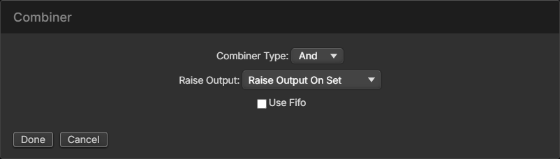
Setting | Description |
|---|---|
Combiner Type | The types that suit the Combiner's number of inputs. |
Raise Output | When the Combiner sends its output on. See Combiner Raise Output Property. |
Use Fifo | Handles the Combiner's inputs one at a time, in the order they arrive, instead of in parallel. See Use FIFO Queue. |
In this case, since the default AND Combiner is a logic gate, the translation types entering and exiting the Combiner are automatically switched to True/False. By assigning a second GPI pin to the second Start Point…
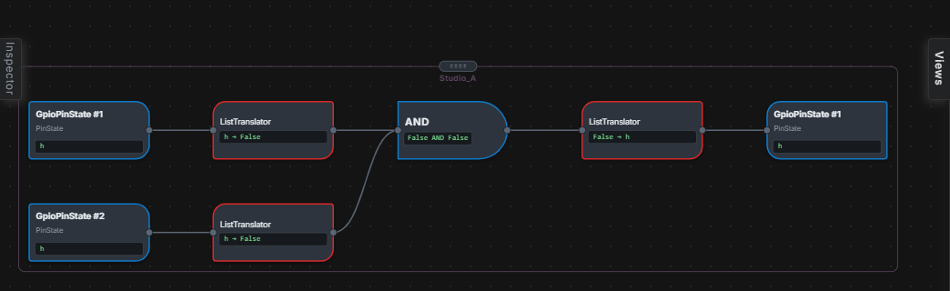
…we can change this event so that two buttons must be held simultaneously for the End Point change to happen. This Flow will set the GPO Low only if both GPI 1 and 2 are Low.
As it is, this Flow is not very useful, but if we change the End Point to a route destination, it becomes more interesting. To do so, double-click the End Point and, instead of a GPIO, expand the Routers section and select the CurrentSourcePath property of one of the router destinations. Then edit the translation after the Combiner so that True translates to one of the sources in the right-hand drop-down of the translation dialog. Remove the False translation because we do not want to do anything if the buttons are released.
This means a user must hold two GPIO buttons down at the same time to route the selected source to the destination. This is a common scenario where we don’t want an accidentally bumped button to change the air chain routing.
Logical Combiners
Logical Combiners include AND, OR, NAND, NOR, XOR, XNOR, and NOT. All of these except NOT accept multiple inputs, which must be translated to True or False on the input side. NOT accepts only a single input. In each case, the translation that feeds the input of these Combiners should be converted to a True or False, as we did in the example above.
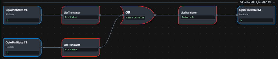
The output of the Translator then becomes either True or False based on the truth table associated with the logical type selected.
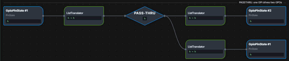
PASSTHRU
The PASSTHRU Combiner allows only one input but can pass the value from the Start Point translation to as many output Translators as you like, allowing you to change multiple output properties based on a single input property.
RELAY
The RELAY Combiner allows you to define one Start Point property that will translate to a True or False. If it evaluates to True, the value from the second Start Point is passed through the Combiner to any translations on the output of the Combiner.
The diagram within the combination displays which Start Point translation is acting as the trigger and which is acting as the PASSTHRU:
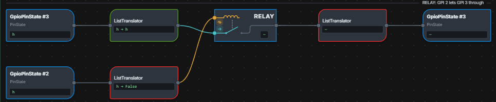
This will achieve the same functionality as our previous example but in a different way. GPI 4 pin 2 must be Low for changes on GPI 4 pin 3 to pass through. If it is Low, changes from GPI 4 pin 3 will be passed to the output translation, which converts the value to a GPO change.
EQUALITY
The EQUALITY Combiner takes multiple inputs and will result in an output value of True or False depending on whether all input values match.
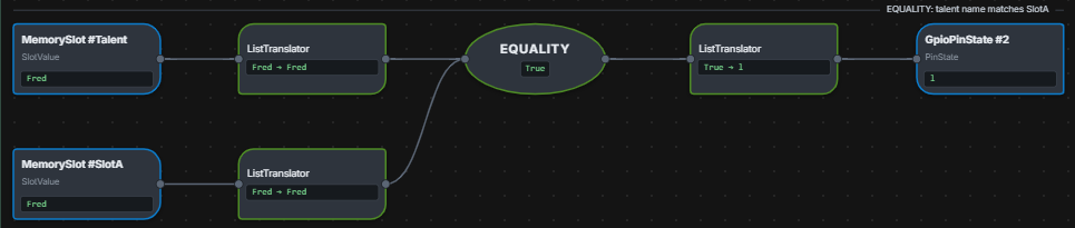
The EQUALITY Combiner also has a Case Insensitive checkbox which defines whether comparisons are case-sensitive or case-insensitive:
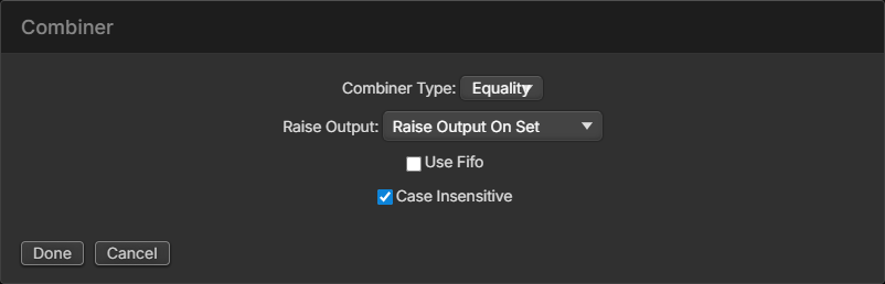
This Combiner can be used in situations where the primary concern is whether the property states are equivalent or not.
DELAY
The DELAY Combiner takes a single input and introduces delay directly into the Logic Flow. It works like a PASSTHRU Combiner in that it takes the input value and passes it through to the output, but only after a configured number of milliseconds. Additional parameters affect how this Combiner functions:
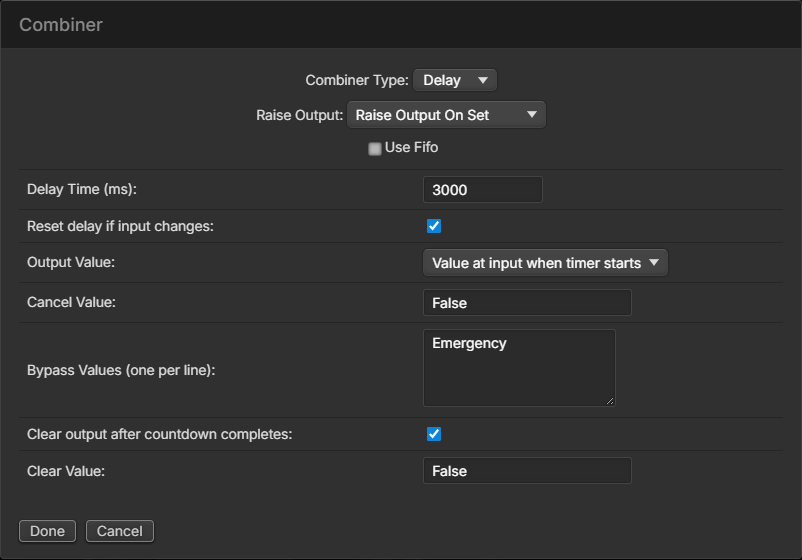
Field | Description |
|---|---|
Delay Time (ms) | Type the Delay duration in milliseconds. |
Reset delay if input changes | The delay countdown starts every time the input changes its value. If this option is selected, the countdown is reset whenever the input value changes. If you have a parameter that is fluttering and you only want an action to happen if it settles down to a fixed value for more than x milliseconds, this option should be checked. If you want the value to happen x milliseconds after a change even if additional changes happen during the countdown (delay time), then this option should be unchecked. |
Output Value | From the drop-down list, select the option that defines whether the value that is passed through is the input value at the start of the delay countdown (Value at input when timer starts) or the end of the countdown (Value at input when timer ends). This option accounts for the possibility that the input value could change again during the delay countdown and allows you to define which value gets passed through. |
Cancel Value | Type an input value that will cancel the timer and not make any change to the Combiner output (not pass any different value through). |
Bypass Values (one per line) | Input values that skip the delay and go straight to the output. A Cancel Value still takes priority over a bypass value. Bypass values are matched regardless of case, and Clear output after countdown completes still applies to them. |
Clear output after countdown completes | Makes the DELAY Combiner function in a momentary fashion. See the example below. |
Clear Value | Type a specific value as the clear state when the clear output after countdown completes option is selected. |
DELAY Combiners can be used in many situations where you need to introduce some delay into a Logic Flow. Previously, this required an interval timer. In many situations an interval timer is no longer necessary, because the delay can be built directly into the Flow. This also reduces licensing requirements, because the DELAY Combiner does not require an intermediary timer End Point.
Interval timers are still useful in situations where a single delay needs to be stopped, started, reset, or manipulated by different Flows.
DELAY/EQUALITY Flow Example
For example, an EQUALITY Combiner can output True or False depending on whether two silence alarms are in the same state. This can be useful if two audio channels should have the same audio. Silence is expected in certain situations, but we are trying to make sure that if audio is present on one, it is present on both, and if it is silent on one, it is silent on both. True or False is translated into a message of AudioMatches or AudioDiffers. A delay is introduced to filter out short variations of alarm states and pass on only definitive states. This is one example of how the DELAY and EQUALITY Combiners might be used.
DELAY Momentary Example
In many cases, you may want the DELAY to pass a value through after the delay but then reset the output for the next change. For example, if we want a Flow that requires a user to hold a button down for a length of time before making a change, the Flow might look something like:

Our goal with this Flow is the following:
If the button is pressed, start a 3-second timer
If the button is released, cancel the timer
If the button is held for 3 seconds, make the GPO change
The DELAY Combiner has an input value and an output value. Changes only get passed to the output Translator when the Combiner’s output value changes. The delay is only analyzed for countdown when the Combiner’s input value changes. For this example, we would set the DELAY Combiner parameters as shown in the dialog above: a 3000 ms delay, a Cancel Value of False, and Clear output after countdown completes checked with a Clear Value of False.
If the user presses the button, the input value gets set to True based on the inbound translation.
The timer starts counting.
If the user releases the button before the timer elapses, the input value of the Combiner gets set to False. Since this matches the cancel value, the delay timer stops counting.
If the user does not release the button for 3 seconds, then the True value gets passed to the Combiner output, which is monitored by the output Translator.
A GPO change is made.
Since the Clear Value and Clear Output after countdown completes options are set, the output value of the Combiner is then set to False again so it is ready for the next button press.
When the user releases the button, the Combiner input is set to False but because that is the Cancel value, no change to the Combiner output is made.
Without the Clear Value and Clear Output after countdown completes options, the output of the Combiner would remain True, so the next press would not change the output and would not trigger another change.
If we cleared the Cancel value and did not use the Clear options, releasing the button would pass False to the output, but 3 seconds after the button was released. A Cancel value, if set, cancels the countdown, but the Cancel value is not passed through.
These parameters let you produce different effects with the DELAY Combiner, depending on your goal.
Going Crazy
By adding Combiners and Translators you can make any individual Flow as deep as you need it to be. You can theoretically continue to add Translators and Combiners as needed to get the logical job done. Translators and Combiners must alternate. You cannot have a Combiner next to a Combiner or a Translator next to a Translator, but the user interface helps with that by only enabling the controls you can use depending on which logic block you currently have selected.
EAS Example
Another relevant example is EAS. A common EAS Flow that customers build translates a GPI from the EAS unit to a route: when the GPI goes Low, the EAS source is routed to the air chain, and when it goes High, the Previous source is routed back.
Important Note: If you use a Flow like this, it is critical that you also turn on the Skip startup state request and wait for next change option. See the Advanced Options section on this option.
If this option is not enabled, a restart of the system requests the current GPI state, which is High, and therefore toggles the Previous route. In many cases this will route “nothing” to the air chain because no previous state exists yet.
However, even with that option enabled, this Flow may produce unforeseen results. For example, what happens if the GPI goes Low and someone manually changes the route before it goes High again? At that point, EAS is the previous source when the GPI does go High. This can be solved by using a slightly more complex Flow and Previous, where a route to Previous will only happen if the GPI is High and we are currently on the EAS source. This is much more reliable.
While these examples have been EAS-related, the same rules apply to other uses of previous. More importantly, if you can avoid the use of Previous and design the Flows to be more specific, the outcome will also be more reliable.
Extending Flows
If you select the End Point of a Flow, you will notice that the End shape control in the control panel is available. This is called "extending a Flow." You can create a second Flow whose Start Point is the same as the End Point of the previous Flow. Click on the End Point and then click the End shape control in the toolbar. The second Flow is created with a *=* translation and the first Flow's title. Likewise, you could add a second Flow using the + button and then set its Start Point to the End Point of the first Flow.
The editor shows the connection with a dashed shared link from the first flow's End Point to the second flow's Start Point (see Shared Links). For example, the lower flow here sets a StudioStatus memory slot from a GPI, and the upper flow, extended from it, lights an on-air GPO whenever the status is On Air:
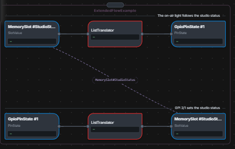
In the same way, a first Flow could route a source to a destination when GPI buttons 1 and 2 are held down, and a second Flow could then turn a button's indicator on if that source is routed to that destination. If anything else is routed to that destination, the indicator will be off.
Cut, Copy, and Paste
Cut, Copy, and Paste are standard tools and require little explanation. You can select a Flow by clicking in the area surrounding it, at which point the cut and copy icons become available. "Cut" removes the Flow from the View and places it on the clipboard, while "Copy" just makes a copy of it on the clipboard. Once a Flow is on the clipboard, it can be pasted back into the current View or any other View.
The system makes some assumptions when pasting. If you copy a Flow and paste it back into the same View, the system assumes you are trying to duplicate the functionality with a new set of End Points. It will clear the outer Start and End Points of the pasted Flow so you can select new ones.
Remember that none of the changes in a cut, copy, or paste operation take effect on the system until you click the Apply button, and that clicking the Clear button returns to the last known applied state. You can also step back through your changes with Undo.
Flow Titling
Each Flow can be assigned a title. If you double-click in the whitespace surrounding a Flow, below its cards, the Logic Flow Title dialog will ask you for a title for the Flow. Click Save, then click Apply to apply the title. Flows that have titles display the title above the right-hand end of the Flow.
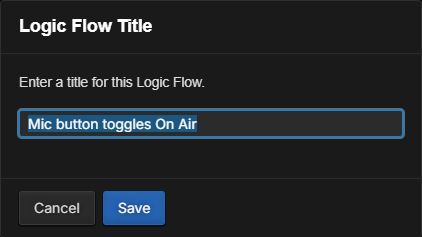
Titling is an important habit to form because it makes it much easier to glance at a Logic Flow View and understand the states of the Flows and which Flows are performing which functions. Titles are also found by Search flows.
Shared Links
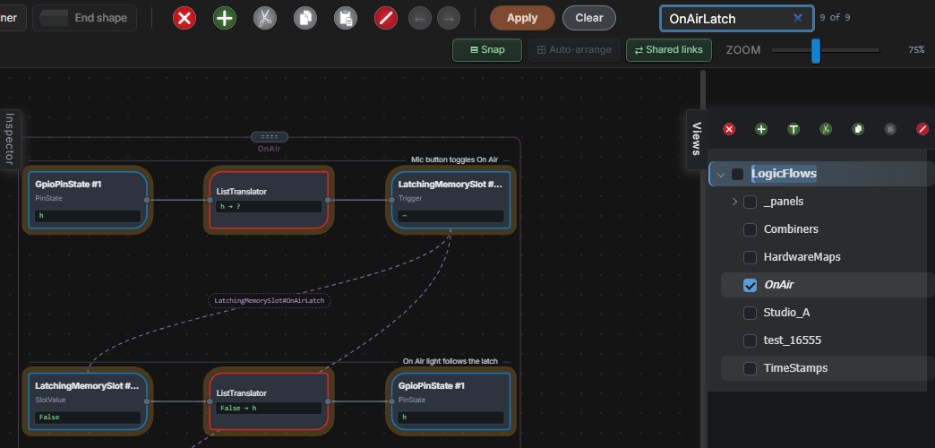
When several flows write and read the same object, such as a memory slot, the editor draws a dashed shared link from the card that writes the object to each card that reads it, across flows and across Views. The link is labeled with the object's name.
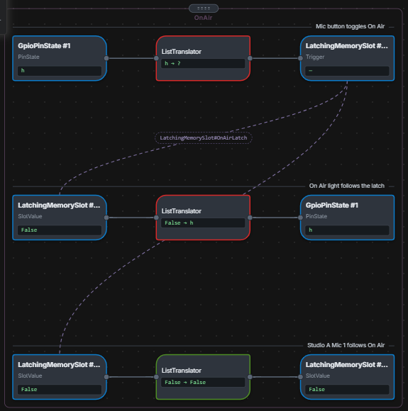
In this example, a GPI toggles the OnAirLatch memory slot, and two other flows read it: one drives the on-air light, and the other sets a microphone's live state.
Click a link's label to highlight everything involved. The Inspector describes the shared object and lists every element that writes or reads it:
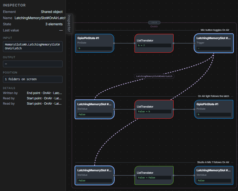
When some of the flows that use the object are in Views that are not shown, the label says how many.
Turn Shared links off on the toolbar to hide the links.
Disabling/Enabling
Translators, Combiners, and entire Flows may be enabled or disabled. Select the Translator, Combiner, or entire Flow (by clicking in the whitespace within the Flow), and then use the Disable button on the control panel.
This change is the only one that takes place immediately within Pathfinder Core PRO Logic Flows without the need to click Apply. The object is grayed out and no longer functions, stopping the Logic Flow at that point. For example, here the upper Flow is disabled:
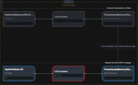
If a Combiner is disabled and you trigger the GPIs, their states will change within the attached Translators, but the End Point will not change because the Combiner is disabled. This is a useful tool if you are testing logic up to a point but do not want the End Point (which might be an air chain change) to change. It is also useful if you want to temporarily disable a Flow during testing or troubleshooting.
Blocked Views
A View can be blocked with Block Execution, for example during maintenance. Its flows keep showing their live inputs but do not act on them. A blocked View's name is shown in red in the Views tree:
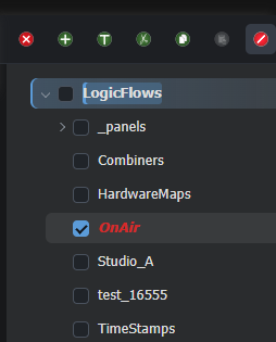
Block Execution is set from System > Configuration, not from the Logic Flows editor. See the Block Execution chapter.
Cluster Disabling
If your system is clustered, the upper right corner of the toolbar will show an Event System state. On the server that is currently in control of the event system, you will see:

On the other server:

This shows that the final output will not execute on this server because the other server is currently in control of the event system.
Important Note: The event system is never actually turned off in Pathfinder Core PRO. When a Logic Flow needs to make a change to an End Point, it first checks whether it has the lowest IP address of the currently active and online servers in the cluster (unless Override Primary chooses another). If so, it executes the action. If not, it does not.
The Event System True or False state is hidden on systems that are not in a cluster, because in that case the clustering system does not disable the Logic Flow End Points.
Object Translators
You may notice when editing the Start or End Point of a Flow that if you select an object in the property selection tree (arrow icon) instead of a property (green dot icon), you will get a warning message that looks like:
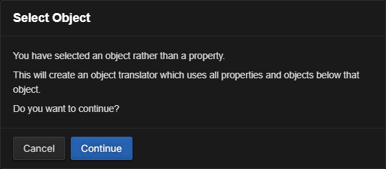
Object translations are a slightly more advanced subject and should be used with caution (hence the warning), but they can also be extremely powerful. Object translations will most likely be used in situations where you want to mirror several different property states across a couple of objects. We could create a Translator Logic Flow where the Start Point is GPI port 2 on Pathfinder Core PRO's own GPIO node and the End Point is GPO port 2:

This Translator looks slightly different in that the Start and End Points show only an object, with no property, and the Translator is labeled ObjectTranslator.
If we do not alter the translation pattern from the default *=*, every change to every property of every sub-object under GPI port 2 is mirrored to the equivalent object and property under GPO port 2. For example, if GPI 2 pin 1 goes Low, then GPO 2 pin 1 is also set Low. If GPI 2 pin 4 goes High, then GPO 2 pin 4 also goes High. This allows us to mirror an object’s settings.
When you edit the translation list and select an object translation, there are additional drop-downs that let you specify the object’s properties as well as its values. For example, we could change the translation pattern from *=* to:
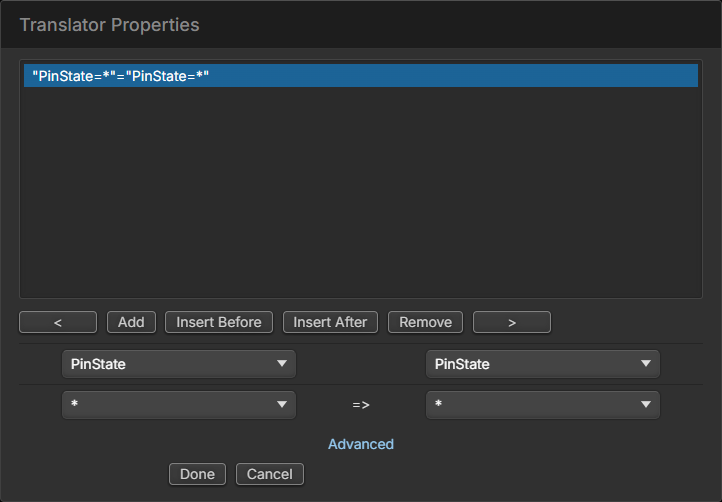
In this case, we are specifying that we only want this translation to operate on PinState properties. If GPI 2 pin 3’s PinState property changes, so does GPO 2 pin 3’s PinState property. Other properties would not be affected.
Or, we could apply values such as:
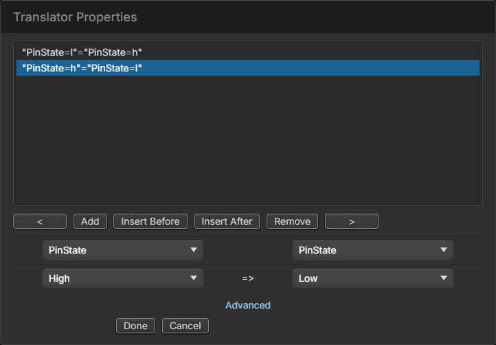
This allows us to invert the states on the GPO port. Now when GPI 2 pin 5 goes Low, GPO 2 pin 5 goes High, and vice versa.
Regular expressions cannot be used in object translations; the dialog warns you if you try.
Another useful way to use Object Translators is when you want to set multiple properties on an object. For example:

In this case, the Start Point is a normal property (GPI 4 pin 1), but the End Point is an object selection (the Air GPO 2 destination on the GPIO_Pins router). If we click on the translation properties, we can make the configuration look like this:
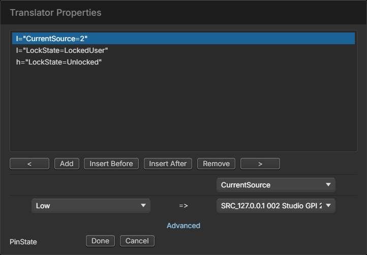
In this case, we are setting different properties on the destination each time the GPIO pin state changes to High or Low: when the GPI goes Low, source 2 (Studio GPI 2) is routed to the destination and the destination is locked, and when it goes High, the destination is unlocked. This can simplify the Flows and greatly reduce the licensing counts used when there are many properties that need to be set.
Object translation is extremely powerful in situations where you want to match multiple properties across two similar objects or multiple properties on a single object.
Latching
A button often needs to latch, so that each press toggles something back and forth. Using the kind of logic shown above to accomplish this can get complicated because the state becomes a condition which is also an action. For example, many novice Pathfinder Core PRO users may try to create Flows that look like this:
Warning: Do not use these Flows. This is an example of what NOT to do!
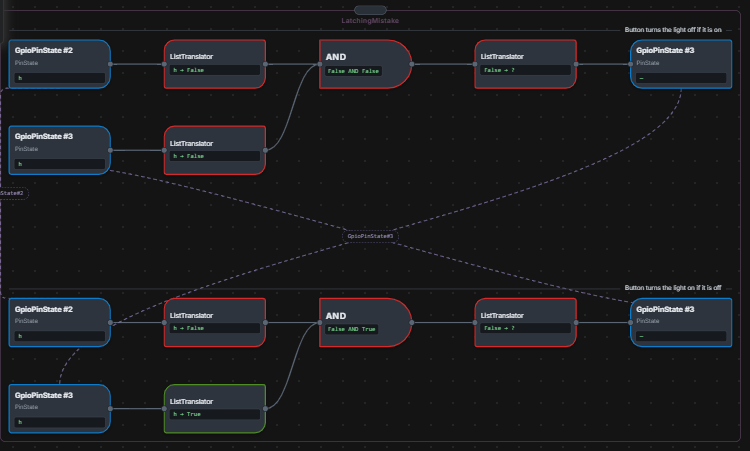
The goal of these Flows is to toggle the state of an on-air light (GPO 4 pin 3) between on and off each time a GPI (GPI 4 pin 2) goes Low.
The user has tried to create Flows where if the GPI is Low and the light is on, it turns off, and if the GPI is Low and the light is off, then it turns on. The problem is that this creates a loop that lasts as long as the GPI is Low.
Setting the GPI to Low changes the state of the light, which in turn causes the other Flow to change it again, and so on until the GPI is returned to High. Trying to solve what appears to be a simple problem this way leads to convoluted loops. To avoid this scenario, we have built two much simpler approaches to latching in Pathfinder Core PRO.
Swap
Many of the properties that have two states (On/Off, Low/High, etc.) also have a value that you can set called Swap. For example:
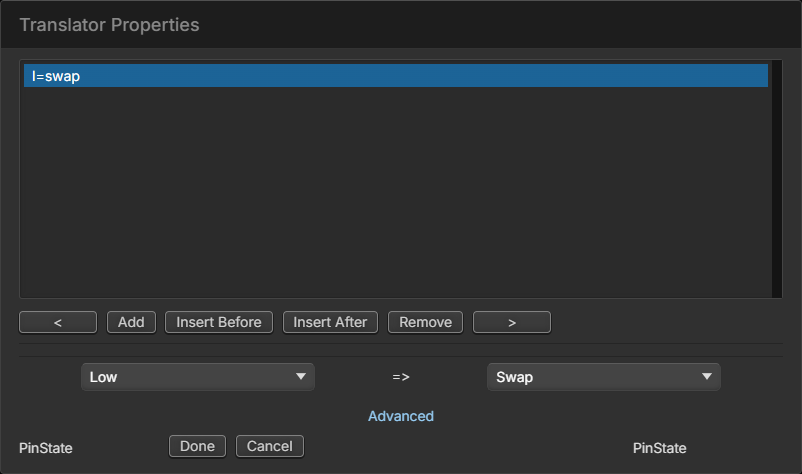

In this case, each time the GPI goes Low, the GPO state will be swapped (Low to High or High to Low).
If a Swap value is available, it is always preferable to other options.
Latching Memory Slot
To achieve similar behaviors for properties that do not have the Swap value, you can use the Latching Memory Slot. While basic memory slots can be created using the Logic Flows property tree as a shortcut, there are additional types that can only be created from the memory slots page as outlined in the Memory Slots chapter.
To create latching functionality, go to Automation > Memory Slots in the navigation bar and add a new memory slot using the Add + button. In the resulting dialog, switch the memory slot type to “Latching Memory Slot”. Provide a name for the slot and click Apply to create the slot.
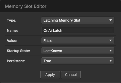
The latching memory slot can only have a value of True or False. It also has a property called "Trigger," which is write-only and cannot be read. Whenever you apply a True value to it, it automatically switches the SlotValue property of the memory slot from True or False to the opposite state. For example, in Logic Flows we could now add a Flow such that whenever GPIO 3 pin 1 goes Low, the Translator sets the trigger property of the OnAirLatch slot to True.
Next, we can create Logic Flows that define what we want to happen depending on whether the latching memory slot is True or False. For example:
Now the GPI will cause the latching memory slot to switch back and forth between True and False. One Flow sets the on-air light GPO from the slot's value, and another sets Studio A's Mic1Live slot.
For a button on an HTML5 user panel, the panel designer's Make latching command creates the latching memory slot and both flows for you. See the User Panels chapter.
Swap over Latching Memory Slot
Again, Swap is preferable where it is available. For example, consider a Flow where the Trigger property causes the latching memory slot to Swap between True and False each time the GPI goes Low, and then that True or False is translated to the on/off state of a console fader. Engaging the GPIO repeatedly will cause the fader to turn on and off. The problem with this Flow is that the fader can also be turned on and off with the actual console button, which causes the latching memory slot to get out of sync with the fader state. This could be solved with a third Flow if we allowed you to force the state of the memory slot each time the fader state changed, but this requires numerous Flows and the creation of a memory slot for every instance of this functionality. This approach is too complicated for what should be a simple task.
The Swap value makes this much simpler and is all that is needed to solve this problem. This is the same Flow shown under Swap above, with the console fader's ON_State as the End Point in place of the GPO:
Each time the GPI goes Low, a value of Swap is sent to the fader. The device manager picks up this request, checks whether the fader is currently on or off, and sends the opposite state as a command to the equipment. The problem with the earlier Flows is that the Flow logic had to encapsulate all viable options of the existing state and specifically request what state to move to accordingly. The Swap property removes that complexity from the Flow logic and allows the system to handle it for you.
The Swap value is an action, so it appears only in the translation options for an End Point. It has no meaning for a Start Point because it is not an actual state there, so it does not appear in the options on a Start Point. The user interface will present the option only where it is available. For example, in the translator shown under Swap above, the left (Start Point) drop-down offers only Low and High, while the right (End Point) drop-down also offers Swap.
Important Note: Axia LCD buttons and user button indicators are a special case because they have more than two options, including On, Off, Flash, Wink, and a variety of other flashing states. However, we chose to add a Swap value to this property because On and Off are the states that are most often used. If a button indicator is Off and the Swap value is sent, the indicator turns on. If it is in any other state when the Swap value is sent, the indicator will be turned off.
Device-Specific Parameters
Infinity Product Support
Detected devices identified as Infinity products have a SendToRestAPI property which can be used by Logic Flows to address the Infinity Rest API. Commands sent to this property use this format:
Operator Path ValueFor example:
PUT /api/s/main/audio/speakerMute TrueGets have not yet been implemented because we do not want to encourage polling logic. You also need to know whether the value being sent must be wrapped in quotes.
Contact Telos support for details on properties that may be manipulated using the Infinity Rest API.
Z/Ip One Control Points
Dialing and status items are exposed in the Logic Flows simple tree under the Z/Ip One branch.
Selecting Start Points
When viewing a Start Point, there are several options:
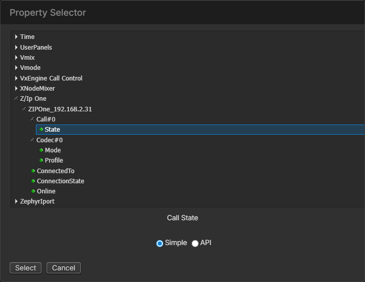
It is important to understand the difference between Call#0 > State and ConnectionState. Call#0 > State lists all possible connection statuses, including multiple options for Idle and options for how the connection was established. ConnectionState offers only Idle, Connecting, and Connected options, making it suitable for situations where logic needs to be fired based on the connection being active or disconnected.
The ConnectedTo property will contain the phone book entry matching the one selected in the Call Connect property, allowing you to display the phone book entry name of the current call connection.
Important Note: In addition to these properties, the API tree contains a much larger set of properties matching those from the Z/Ip One Lwcp API. Consult the Z/Ip One documentation for details on these other properties.
Selecting End Points
When selecting an End Point in the Simple tree, the Z/Ip One branch includes several properties for any Z/Ip One in the system:
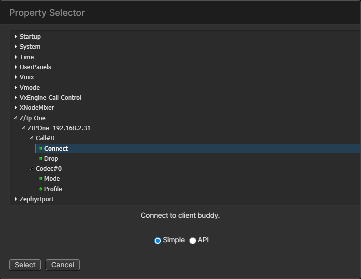
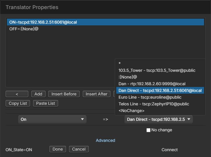
Connect and Drop can be used to establish and drop connections. After selecting the Connect property as a Logic Flow End Point, the translation list will display the list of entries in the Z/Ip One phone book. Currently, only phone book entries may be used for dialing:
Important Note: In general, the Codec settings will not be used as an End Point since those settings are normally stored within the call phone book entries.
There is also a special phone book entry called None that exists only in Pathfinder Core PRO and, when dialed, behaves the same as the Drop item.
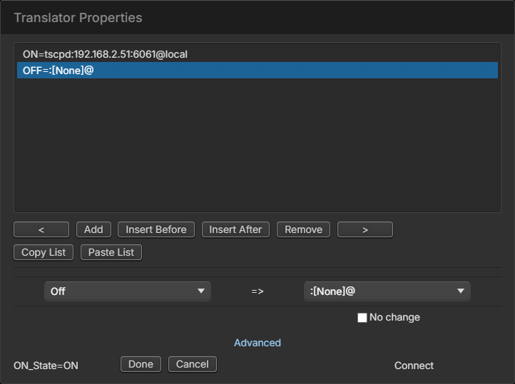
For example:
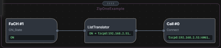
This Flow will dial the Z/Ip One every time Fader 1 is turned on and drop the call every time it is turned off.
Zephyr iPort Control Points
The iPort branch in the simple tree exposes the Encoder and Decoder Enable and Disable options. We have limited those options to the simple tree because most other properties related to the iPort MPEG side of the configuration are considered advanced and are not normally dynamically adjusted.
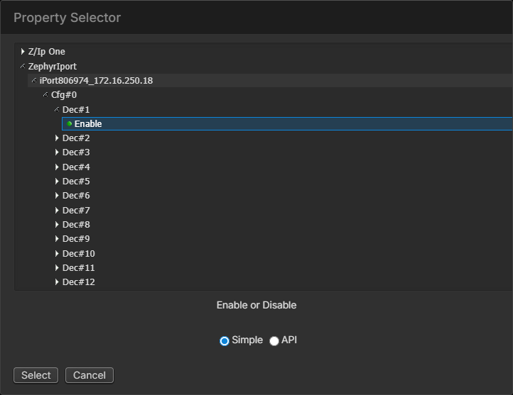
Most of the other settings found on the Configuration pages of the iPort are available via the API.
VX Control Protocol
The VX and its control protocol need some additional explanation. This protocol allows Pathfinder Core PRO logic flows and user panel controls to monitor and change VX calls in a studio. Control points such as lines, studios, call states, comments, and call actions are available to Pathfinder Core PRO through this protocol.
It is important to understand that when you connect to a VX engine on the control port, you have to select which studio to interact with. As a result, if you want to monitor multiple VX engine studios in Pathfinder Core PRO at the same time, a separate TCP connection is required for each studio. Rather than enabling this by default when many customers may not need this functionality, we decided to allow the administrator to enable the studios they wish Pathfinder Core PRO to interact with and leave the others disconnected. This conserves resources.
To begin using the VX Control protocol, go to the Logic Flows tab and select a logic flow view. Add a flow and double-click the end point. Within the tree you will see a new branch called VxEngine Call Control.
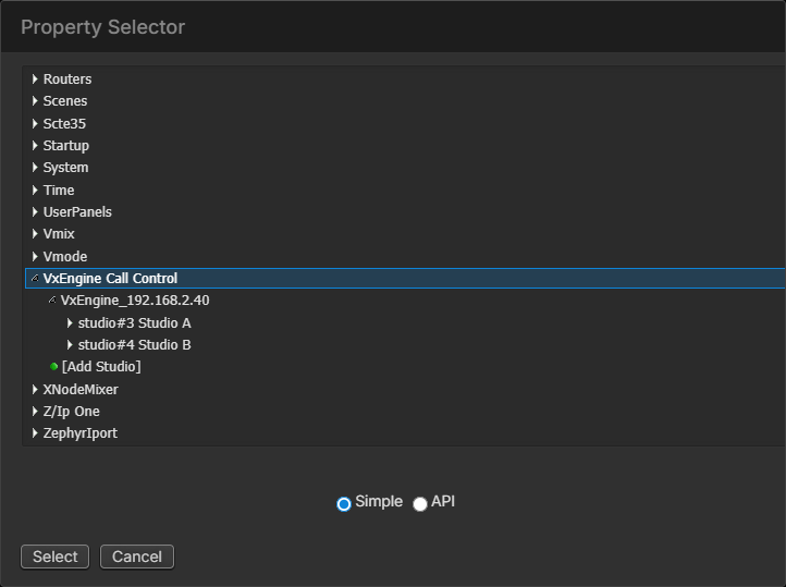
Click the [Add Studio] branch to open a dialog where you can select which studios you want Pathfinder Core PRO to use and monitor.
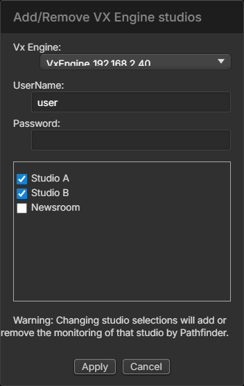
Select the VxEngine whose studios you wish to enable from the drop-down, then enable the checkboxes for the studios you wish to have available. You need to click apply for each engine whose studios you enable or disable. If you have changed the Lwcp password in the VxEngine, you need to supply the correct password in this dialog as well. If you change the password after adding the studios into Pathfinder Core PRO, come back to this dialog, deselect the studios and apply, then reselect them using the new password and apply again. This dialog is not specific to this instance of logic flow editing. You are adding or removing that studio support from the system and so it is generally a one-time change, but it does require some CPU resources while adding or removing the studio. We decided to place this dialog within logic flow because that is where customers will most often work with the VX Control protocol data points.
Once added, the studio and property items will then be available in logic flows under the specified engine:
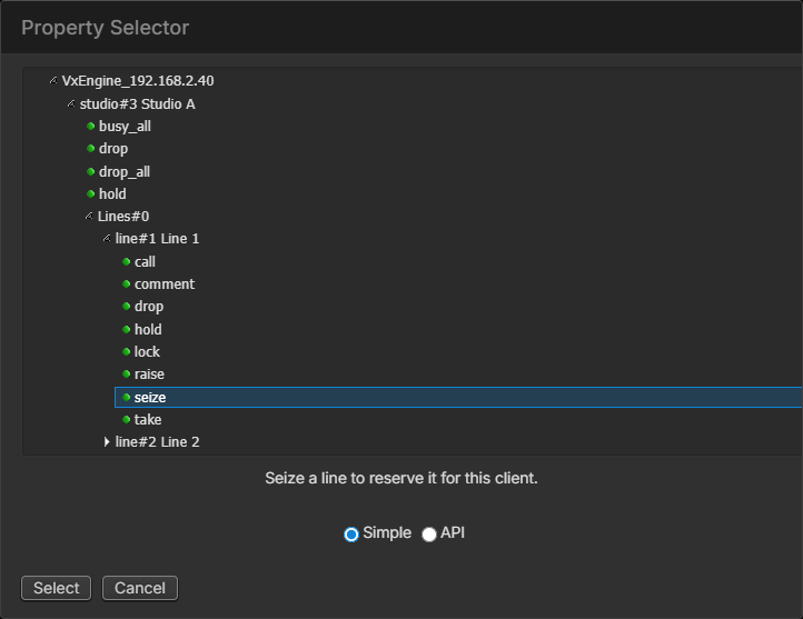
Warning: If you add new studios to an engine, you need to collapse and re-expand the engine branch to see the new studio. Also, if you uncheck (remove) a studio, you may need to refresh the logic flows web page before it is removed from the property tree. Removing (unchecking) a studio removes it from Pathfinder’s control and monitoring entirely, which may affect any other flows that use that studio.
Gpio Ring Example
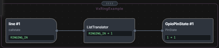
As an example of how this might be used, you could have a GPIO light an indicator whenever a given line rings. To accomplish this, you would create a flow where the start point is the line’s callstate property and the end point is a GPIO.
The flow would look like:
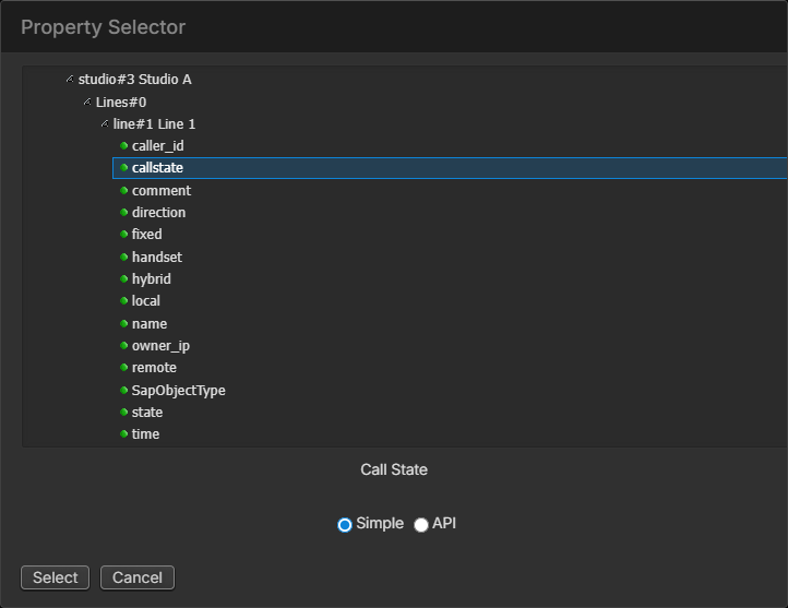
For the translation you would create something like:
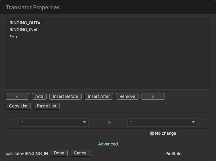
Additional flows could be added to trip other GPIO pins for different lines.
The properties differ significantly depending on whether you are selecting a start or end point. There are numerous properties that are “read only” or “write only” and so will only display in either the start or end point editing. Selecting a property in the logic flows tree will also display a brief description of what the property does.
Panel Example
You can also use these properties in user panels. For example, you could use a label object and bind the label’s background color to the line call state and the textContent to the caller_id field. A button could then be used to answer and drop the calls. One of our support engineers built the following using the HTML5 user panel designer during our initial testing.

This uses a large label where the call state is bound to the background color, and smaller transparent labels on top of that are bound to the caller_id, comment, and time properties. An image was also overlaid that swaps between multiple images to represent call state. Finally, additional buttons were added for the additional call actions such as seize, drop, and hold. Using these items, you can develop a user interface to your liking that works with the VX phone system. This also allows you to create a user interface that mixes console fader control, call control, and other user interface items to achieve your specific needs.
Available Properties
The table below lists the commonly used properties. Additional properties may be available that are not included in this list, so review the logic flow tree and property descriptions within the tree. Items in this table whose syntax is True only are write-only actions, where setting the property to true is a momentary state that triggers the action.
Object | Property | ReadWrite | Description | Syntax |
|---|---|---|---|---|
Line | call | W | Call out using a specific hybrid. | <hybridnumber>_ <numbertocall> |
Line | caller_id | R | Caller Id | Text |
Line | callstate | R | Call State | List of states |
Line | comment | RW | Comment for the Line | Text |
Line | direction | R | Direction for the Call | NONE INCOMING OUTGOING |
Line | drop | W | Drop a line | True |
Line | fixed | R | Is line fixed or selectable | True/False |
Line | handset | R | Is call on the handset | True/False |
Line | hold | W | Hold a line | ON_HOLD_READY ON_HOLD |
Line | hybrid | R | Take the next call to the specified Hybrid | List of hybrid ids by name |
Line | local | R | Local Phone Number | Text |
Line | lock | W | Lock a line | True/False |
Line | name | R | Name of the Line | Text |
Line | owner_ip | R | IP address of the current line owner | Text |
Line | raise | W | Raise a line in priority | True |
Line | remote | R | Remote Phone Number | Text |
Line | seize | W | Seize a line to reserve it for this client | True |
Line | state | R | Line State | List of states |
Line | take | W | Take the next call to the specified hybrid | List of hybrid ids by name |
Line | time | R | Line Time | Time |
Studio | busy_all | RW | Sets and reads studio busy_all state | True/False |
Studio | drop | W | Drop a specific hybrid | List of hybrid ids by name |
Studio | drop_all | W | Drop all calls | True |
Studio | hold | W | Hold the call that is currently on a specific hybrid | List of hybrid ids by name |
Studio | message | RW | Instant Message | Text |
Studio | mode | W | Set the studio mode for backward compatibility | TALENT PRODUCER |
Studio | mute | RW | Studio Mute | True/False |
Studio | show_id | RW | Set or read Show Id | List of show ids by name |
Studio | take | W | Take a call | True |
Studio | next | R | Position of line that should be answered next | Number |
Quasar 4 fader panel QSCONN Lwrp Object
Each Quasar 4 fader panel device type has a QSCONN property within the LWRP protocol. If you already have Quasar fader panels in your system, before upgrading to 1.18, you may need to remove them and re-add them to get the correct object type. If they appear in your devices list as Quasar_4-Fader instead of QuasarFader4, you might need to remove and add the panel to Pathfinder Core PRO again.
The QSCONN object is accessible via the API tree in logic flows under the Devices\<QuasarFaderPanelDevice>\LwrpInterpreter\LwrpRoot\QSCONN path. It is not commonly used, so it does not appear in the simple tree. It has two properties:
Master (RW): Holds the IP address of the master module to which this fader bank is attached.
Status (RO): Whether the Fader panel is currently connected or disconnected from the master panel.
The Master property may be set to a new IP address to change which master module the fader panel is connected to. This functionality should be used with care and discussed with support to be sure you understand the ramifications, but it can be used to make a fader module address a different master module dynamically.
Additionally, in the current version of Pathfinder Core PRO code and Quasar code, this Fader Module does not push changes to Core PRO. As a result, status and master changes made in the web page of the device may not be reflected in Core PRO until the next poll time. Additionally, changes made to this object by one Pathfinder Core PRO server may not be detected by a second server until its next poll time. This limitation may change in future software revisions.
XNodes and FPSTAT
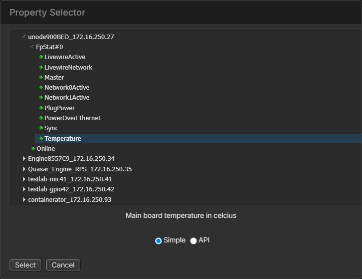
This version adds support for the FPSTAT object in xNodes. The FPSTAT object carries several read-only properties related to temperature, power supply status, network link, etc. It's found in the Simple tree under the DeviceConnections branch and the API tree under the device's LWRP path.
In the current version of xNode software, these parameters require polling to obtain state and do not automatically push changes. By default, Pathfinder Core PRO will poll these properties every 15 seconds.
An advanced option called FpStatPollRate in the System > Configuration > Advanced Options settings changes this. You may need to view the default settings to obtain and override its syntax. FpStatPollRate is a global setting and should only be changed with caution and understanding of the consequences. In networks with many xNodes, decreasing this poll rate can affect the amount of communication that Pathfinder Core PRO needs to process.
The properties available are:
Master: Whether this node is currently clock master, regardless of the actual setting. The xNode could be set to allow it to become a master but not be one currently. 1 indicates Master.
Sync: Status information regarding the clock sync state. A numerical value of the xNode's SYNC indicator. Blank is no SYNC (normal if this device is Master). 12 is fully synced (SYNC is not blinking). 1 indicates furthest away from the synced state. The closer the xNode gets to a fully synchronized state, the higher the number.
LivewireActive: Whether the device is receiving Livewire advertisements.
Temperature: Temperature in Celsius of the main board.
Plug Power: Whether the power supply has power from the IEC plug port.
PowerOverEthernet: Whether the power supply is receiving power from the Ethernet port.
Network0Active: Whether Ethernet port 0 is active (this is NET 1 on the xNode).
Network1Active: Whether Ethernet port 1 is active (this is NET 2 on the xNode).
LivewireNetwork: Which NIC (0 or 1) is the Livewire network.
Use these settings together with the online property, not as a replacement for it. For example, if all power is lost from the xNode, we will likely not see the Plug Power or POE properties change because we will have lost connection to the object that hosts those properties before we could read the change. So we must rely on the online state to know we are no longer connected. On the other hand, if you have both Plug Power and POE power applied and one of them is lost, the status shows online, but we get an alert that one of the supplies is down. Similarly, if you lose connection on the NIC that you are using to monitor this object, then the NIC states in Core PRO for this object will not change. We have to rely on the Online state for that. On the other hand, if you set up the NICs in the xNode to be redundant and one fails, we can detect and alarm this condition.
Advanced Options
Endpoints and the API Property List
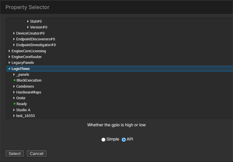
When editing a Start Point or End Point, the property selection dialog has two modes: Simple and API.
The simple tree is what most users should use. It is designed to present the most commonly used objects and properties organized for quick access. Occasionally there may be a job that requires reaching beyond the normal options, and selecting the API tree will present a much wider array of objects and properties.
Pathfinder Core PRO has an advanced protocol called SapV2 which extends beyond most typical protocols and reaches the level of an API (application programming interface). It allows virtually complete control over the system. This API is the protocol used for all internal messaging between system services. To learn more about this API, see the SapV2 appendix.
For this API to do its job successfully, almost every property and object must be available. The API section of the property selection dialog exposes the object and property tree available via that API.
Translator
To configure advanced options on a Translator, click the Advanced link on the Translator Properties window.
Translator Skip Startup State
The expanded Translator dialog contains the advanced Skip startup state request and wait for next change option:
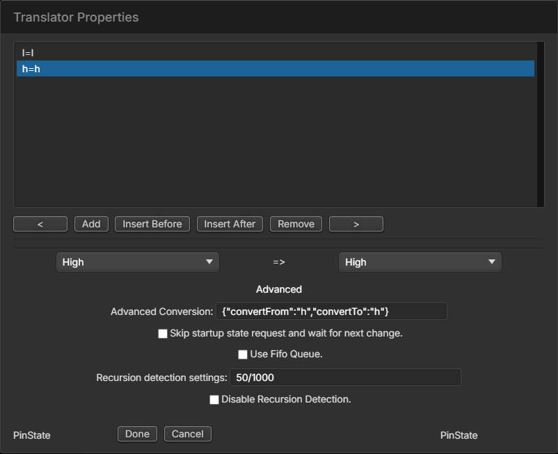
By default, when the system starts (or when a Flow is applied to the system) the Flow asks for the current state of the Start Point and then applies the correct result to the End Point. In most cases this is desirable, but not always. For example, what if the Logic Flow in question had a latching GPIO on the Start Point and an automation system that gets tripped on the End Point?
If we needed to restart Pathfinder during that event, we would not want the automation system to be tripped again. Checking the Skip startup state request and wait for next change option overrides the default behavior and forces the system to wait for the next change that would cause the Flow to execute.
Important Note: When designing a system, test how your logic handles a system or device restart before it goes live on air.
The Skip Startup State option is also important in the commonly used EAS example shown earlier in this section.
New translators start with this option unchecked. To change that default for every new translator in logic flows, routers and user panels, set the SkipStartupStateRequestOnNewLogicFlows property:
set LogicFlows#0 SkipStartupStateRequestOnNewLogicFlows=TrueExisting translators are not changed.
Recursion Detection
If the Logic Flow system detects a given Translator being activated more than 50 times in 1000 milliseconds (the default setting), it assumes recursion is involved and disables the Translator to prevent excess CPU load. In some situations, this can create a False positive. For example:
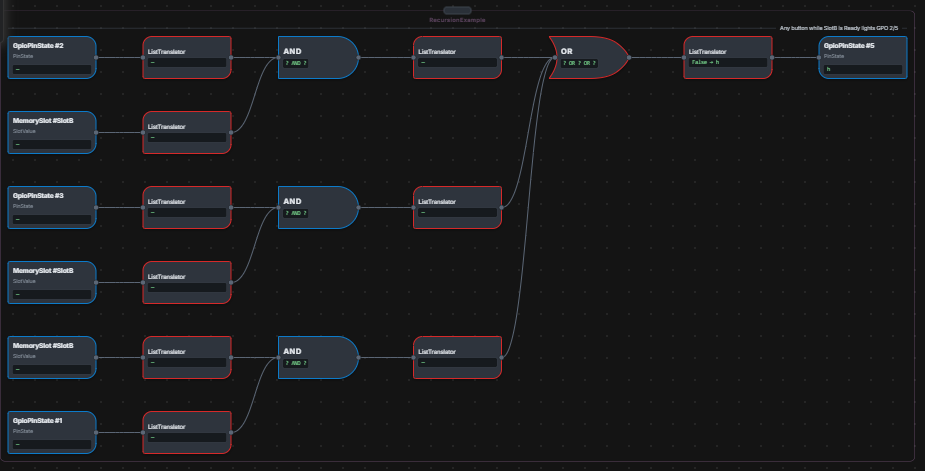
In this Flow, the same memory slot (SlotB) is used for multiple entry points to a Flow, so a change to that memory slot could cause multiple pass-throughs of some Translators. If this Flow were to grow to a much larger variation with many more entry points of the same memory slot, it could trip the recursion detection incorrectly.
Important Note: If recursion detection disables a Translator, a log message is generated and the system tries to send an email message to the critical event email address, if one is configured.
Recursion detection also protects the bindings of HTML5 user panels, which are flows in the _panels View. If it disables one of them, the panel designer shows a warning banner with an Enable button, so you can turn the binding back on once the cause is fixed. You can also turn it back on in Logic Flows: open the _panels View, select the disabled Translator or Combiner, and click the Disable button on the control panel. This is the only change Logic Flows allows in that View.
Recursion detection threshold settings are modified in the expanded Translator dialog.
Check Disable Recursion Detection to turn it off for a translator entirely. Use this with care.
This value includes two parts separated by a forward slash. The first value indicates the analysis frequency; the second indicates the analysis duration in milliseconds. For example, typing 50/1000 will disable the Translator if it is being analyzed more than 50 times per 1000 milliseconds.
Additionally, there is an API property that can change the default recursion settings for all new Translators:
Set LogicFlows#0 DefaultRecursionSettings="50/1000"This setting should be modified with extreme care because it also updates any existing Translators that are currently at the default settings. This can be CPU intensive and require a significant amount of writing to disk. Make a backup before changing this value.
Use FIFO Queue
By default, when several changes reach a translator or combiner at nearly the same time, they are processed in parallel. In rare cases this can let a later change finish before an earlier one. Check Use Fifo Queue in the translator's advanced options, or Use Fifo in the Combiner dialog, to process changes one at a time, in the order they arrived.
This is an option rather than the default because a workflow often reaches beyond the flow you are looking at. For example, a flow may set a memory slot that is used by a router or a panel elsewhere. Use it where the order of changes matters, and test the whole workflow. It is not available on DELAY Combiners.
A queue holds the next change until the current one has finished. The current change is finished when any of these happens:
Its processing ends.
It reaches a delay, such as a DELAY Combiner, and is handed to a timer.
It results in a command being sent to the network.
It reaches another translator or combiner that uses a FIFO queue.
Because of the last rule, two queues on the same path do not hold changes in order from end to end. The second queue releases the first, and the first can pass its next change while the earlier one is still being processed downstream. Build the logic without the option, then turn it on only at the entry point where changes arrive out of order.
Combining the * Wildcard with Other Values
A translator commonly has this conversion list item:
*=*However, the * on the ToValue side does not need to be by itself. For example, you could have:
*=Hello I am *
In this case, the input value would replace the * in the output value. If the input value is Fred, the ToValue example above would output the string Hello I am Fred. This gives the Flow translation functionality similar to string builder memory slots.
The * cannot be used in the middle of data on the "from" side. Use regular expressions for complex matching if needed.
Advanced Conversion Field
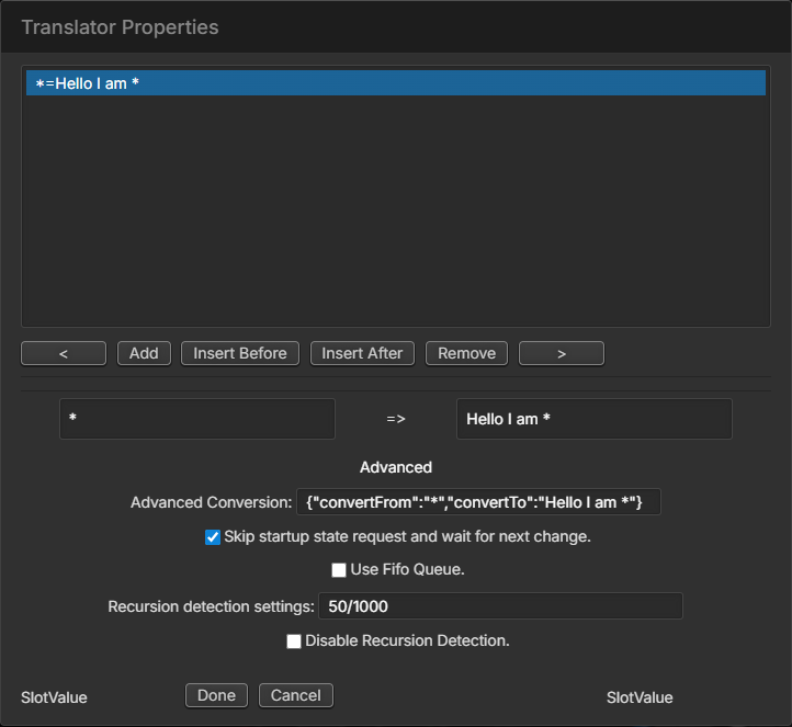
The Advanced Conversion field, available in the expanded Translator dialog, lets you bypass some of the helper dialogs and enter conversion statements directly. It shows the selected entry of the translation list:
While bypassing the helper dialogs can be useful in certain unique scenarios, those dialogs present information that is helpful when selecting a property but may or may not be the underlying value needed in the conversion. For example, when using the CurrentSourcePath property, the conversion list and normal drop-down list will show you the friendly name of the source. However, the actual conversion list item needs the uri based pathio, which looks something like:
"tcp://172.16.1.53:93?l=SRC&d=src&i=6&t=aaudio"If you are uncertain about the value requirement, create an example of what you are trying to do using the normal conversion list selection methods and then select it in the Advanced field to see the actual values that need to be applied. If you have questions, contact support.
Important Note: Incorrectly entering data into this field can cause unpredictable results.
The field shows the selected entry as JSON, with its FromValue and ToValue:
{"convertFrom":"*","convertTo":"Hello I am *"}You can type an entry either in that form or in the shorter form:
<FromValue>=<ToValue>For example:
l=TrueIn the shorter form, if the From or To value needs to include a literal equals sign, then enclose the value in quotes. The From value will be abc=frs in this example:
"abc=frs"=TrueThe JSON form needs no quoting, because the two values are kept apart.
If <NoChange> is applied to the ToValue portion of a translation, the output of the translator will not be changed. For example:
AAA=True
BBB=<NoChange>
*=False
In this case, an input FromValue of AAA will result in True, BBB will not cause anything to change on the output of the translator, and any other FromValue will result in False.
In many cases, a <NoChange> is not required because you can leave that input out of the list, and nothing happens when it occurs. Use it when the * wildcard is your catchall but you want to explicitly exclude a value from making a change.
Important Note: <NoChange> is not applicable to the FromValue side of a translation and will be interpreted literally if entered on the FromValue side.
Translation Regular Expressions
Regular expressions, as described in the Watchers and Regular Expressions section in the Device Emulators chapter, can also be used in the FromValue portion of a conversion list item. Regular expressions are added to the Advanced Conversion field as follows:
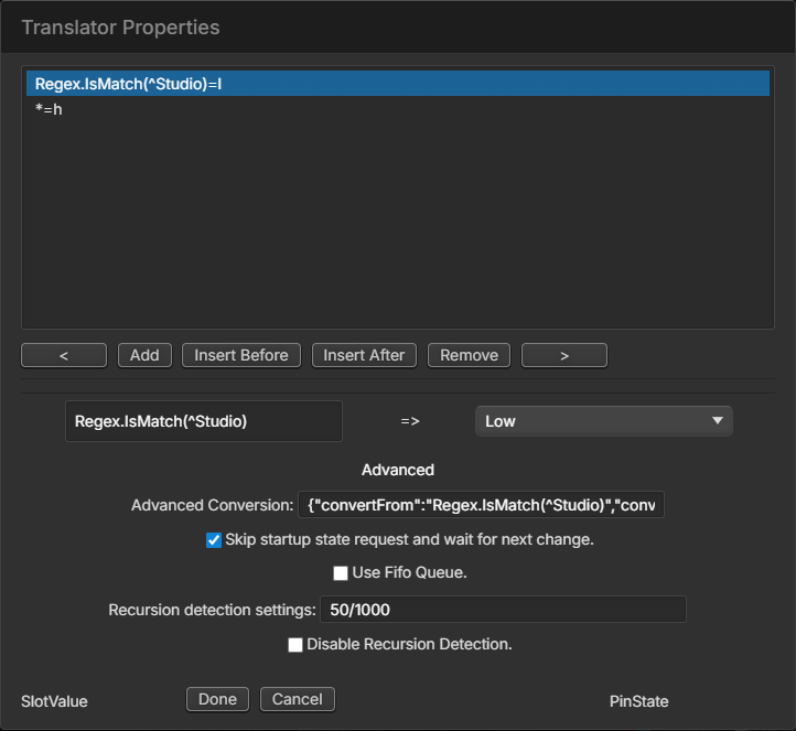
In this example, we are using the IsMatch property. SlotA values that start with Studio will result in GPO 3 pin 4 being set Low; otherwise, the GPO will be set High. Matching ignores upper and lower case.
Regex.Match works the same way, but a * in the ToValue is replaced by the text the expression matched rather than the whole input value. For example, Regex.Match([0-9]+)=Studio * turns Line 12 ringing into Studio 12.
Because a value such as Fader_Gain generates significant data as it slides, you may also need to increase the recursion detection value to prevent such a Flow from getting disabled.
Important Note: Using regular expressions can be slower and more CPU intensive. Use them only where needed and use the normal translations elsewhere.
Combiner Raise Output Property
In the examples above, you may have noticed a Combiner property called Raise Output that we have not discussed yet.
The values for this property are Raise Output on Set and Raise Output on Change. The effects of this property are subtle but important to understand:
In this Flow, if both pin 1 and pin 2 are Low, then the GPO will be set Low. If either pin 1 or pin 2 is High, the GPO will be set High. If the Combiner is set to Raise Output on Set, then any time either pin 1 or pin 2 changes, a message is sent to set the GPO to the corresponding value. So, if we assume the GPO is currently High or Low and we set pin 1 to Low when pin 2 is still High, a message will get sent to the GPO to go High.
However, if the setting is set to Raise Output on Change, no message will be sent to the GPO. When both pin 1 and 2 were High, the resulting output of the AND Combiner was False. When pin 1 goes Low, the resulting output of the AND Combiner is still False. Its output value has not changed, so no message is sent.
The difference is subtle, but essentially with “Raise Output on Set”, a change message will be sent to the End Point any time the input of the Combiner changes, even if it evaluates to the same output as before, whereas with “Raise Output on Change”, a change message will only be sent when the Combiner’s output changes.
Let’s look at another example of when Raise Output on Change could be useful:
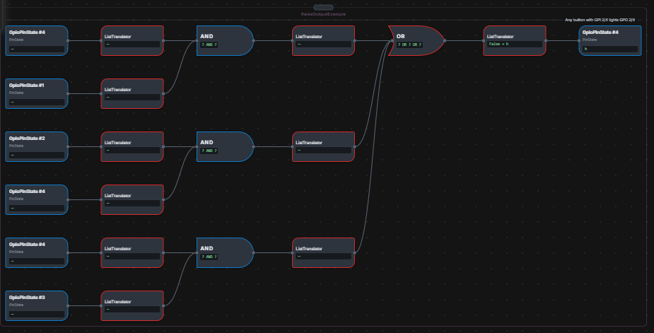
In this example, GPI 2 pin 4 appears at each pair of AND Combiners on the left-hand side of the Flow. The buttons are GPI 1 pins 1 to 3. If all the Combiners in this Flow are set to Raise Output on Set, then the resulting End Point may get set 3 times when GPI 2 pin 4 changes. This is because a change to the pin would get fully passed through the Flow for each instance where it appears as a Start Point. However, if the left AND Combiners are all set to Raise Output on Change, then the output will only get set for Combiners where the pin state change actually causes a different state on the output of the Combiner. This can greatly reduce load and improve performance in large and complex systems.
This property is a new variable that must be stored in the backing storage. For backward compatibility with older software versions, Raise Output on Set is stored the same way it always has been. However, any Flows that are changed to use Raise Output on Change cannot be loaded by older software versions that do not support this property.
For advanced users, it is possible to change all of the Combiners to a particular setting using the port 9600 API. Each Logic Flow View has a write-only property called ChangeAllCombinerRaiseOutputSettings. Using this property, all Combiners in a View and that View’s sub-Views can be set to the same value. This is useful for changing many Combiners at once but should be used with caution. Take a backup before using this API command. For example:
set LogicFlows#0.LogicFlowFolder#yyy ChangeAllCombinerRaiseOutputSettings=RaiseOutputOnSet
set LogicFlows#0.LogicFlowFolder#yyy ChangeAllCombinerRaiseOutputSettings=RaiseOutputOnChange
See the API reference in Appendix 2 for details on how to use these commands.
Simple Tree Commonly Used Properties
Providing a list of every object and property in the system is beyond the scope of this documentation. One of the reasons we provide the description within the property selection dialog is to make the software self-documenting. However, it is useful to describe some of the more commonly used properties here, if only to generate ideas for how to use Flows within your environment. While this list is not complete, we encourage you to spend some time browsing the tree and examining the various available properties and their descriptions. As always, our support staff can help. Remember that because some properties are read-only or write-only, they may be available only for a Start Point or only for an End Point.
Branch | Property | Description |
|---|---|---|
Audio Alarms | AlarmState | Once an audio alarm has been configured, this property shows the current state of the alarm; it can be Unknown, AudioPresent, Silent, or Clipping; logical decisions can be made when this state changes |
Audio Alarms | LvlState | When a silence alarm is configured, Pathfinder Core PRO requests updates whenever the threshold value is passed for more than 250ms; this property carries the current state regardless of the current alarm countdown |
Buttons | BackColorOn | Used to set the backcolor value when the button is on |
Buttons | BackColorOff | Used to set the backcolor value when the button is off |
Buttons | Ind | Used to set the indicator of the button on, off, or in a variety of flash states |
Buttons | Text | Used to set the Text value of a button |
Buttons | Key | This property will be UP or DOWN depending on whether the button is pressed or released |
Console | ShowProfId | The id of the show profile loaded on the console; this can also be used to change the currently loaded show profile |
Console | ShowProfName | The name of the show profile loaded on the console |
Console | Asg_PGM1-4 | Used to set or determine whether a specific console fader is assigned to any of the 4 program buses |
Console | Asg_Prev | Used to set or determine whether a specific console fader is assigned to the preview bus |
Console | Fader_Gain | Used to change the gain of a fader |
Console | MUTE_State | Used to set or determine if the mute state on a fader is engaged |
Console | OFF_But | Whether the Off button on a fader is up or down |
Console | ON_But | Whether the On button on a fader is up or down |
Console | ON_State | Used to set or determine if a console fader is on or off |
Console | src_lwch | Carries the Livewire channel number loaded to a fader |
Console | talkback | Used to engage or sense the engagement of the talkback button on a fader |
Console | tt_cr | Used to engage or sense the engagement of the talk to control room button |
Console | tt_st | Used to engage or sense the engagement of the talk to studio button |
Console | tt_prev | Used to engage or sense the engagement of the talk to preview button |
Console | IND | Used to change the indicator state of user-definable buttons on the console |
Console | KEY | Used to sense the key state of certain user-definable buttons on the console |
DeviceConnections | Connected | This property can be used to sense and react to connection problems with any of the Axia devices |
DeviceConnections | Online | This property senses whether a device is responding to commands |
Body | Used to change the body text of an email message | |
Subject | Used to change the subject of an email message | |
Send | Used to send a predefined email message | |
Emulators | Triggered | Used to determine when a Generic emulator’s watcher detects a defined input value |
Emulators | ToSend | Used to send data out a generic emulator port |
Gpio | PinState | Used to change or sense changes on a GPIO pin |
Memory | SlotValue | Used to sense changes or change the value of a memory slot |
Memory | Trigger | Used to change the value of a latching memory slot from True to False or False to True |
Routers | CurrentSourcePath | Used to sense or activate a route change on a specific destination |
Routers | CurrentChannelNumber | Used to sense the Livewire channel number assigned to a destination. This property can also be used to make router changes using Livewire channel numbers for the source |
Routers | CurrentSourceName | This property is updated with the name of the source that is currently routed to the selected destination |
Scenes | IsActive | This property will be either True or False depending on whether all states in the scene are currently active |
Scenes | ActivateScene | Setting this property to True will make Pathfinder Core PRO initiate all of the changes in a scene |
Startup | StartupFileProcessed | This property can be used to set up certain states after Pathfinder Core PRO has been restarted |
Time | Enabled | Used to enable or disable a timer. Logical decisions can also be made depending on whether a timer is enabled or disabled |
Time | Elapsed | Becomes True when a timer elapses |
Vmix | Gain | Used to sense or make changes to a VMIX fader’s gain setting |
Vmix | State | Used to turn VMIX channels on or off and sense the same state changes |
Vmix | TimeDown | Used to sense or make changes to the length of the fade-out when a VMIX fader is turned off |
Vmix | TimeUp | Used to sense or make changes to the length of the fade-in when a VMIX channel is turned on |
Vmix | Master_Gain | Used to sense or make changes to the master gain of a VMIX submixer |
Vmode | AUDIO_MODE | Used to sense changes to the audio mode state of a VMODE IO |
Vmode | IN_SELECT | Used to sense changes to the IN_SELECT state of a VMODE IO |
Flows, Flows, and More Flows
While this chapter has reviewed the details of Logic Flows, many other chapters of this manual say more about their uses as we detail how each part of the system works and what capabilities may be used.