Click the Routing and Audio > Routers link in the navigation bar to see a list of routers in the system:
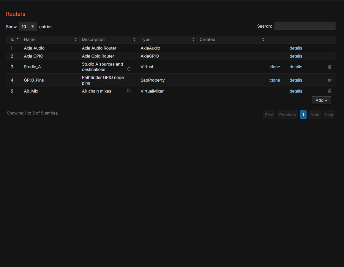
Pathfinder Core PRO currently supports:
Axia Audio Routers
Axia GPIO Routers
Virtual Routers
Virtual Mixing Routers
Sap Property Routers
Imagine Lrc Routers
Telos Metadata Routers
The Axia Audio Router and Axia GPIO Router are automatically generated based on devices discovered in the system. These two routers will always be in the system and cannot be removed. Virtual Routers, Virtual Mixing Routers, Sap Property Routers, Imagine Lrc Routers, Telos Metadata Routers, additional Axia Audio Routers and additional Axia GPIO Routers may be created and removed from the Routers page.
Virtual and Sap Property routers also have a clone link, which makes a copy of the router with all its sources and destinations, named Clone of followed by the original name. This is a quick way to start a router that is similar to an existing one.
Click the Details link for any router to open a new screen with the routing status of the router:
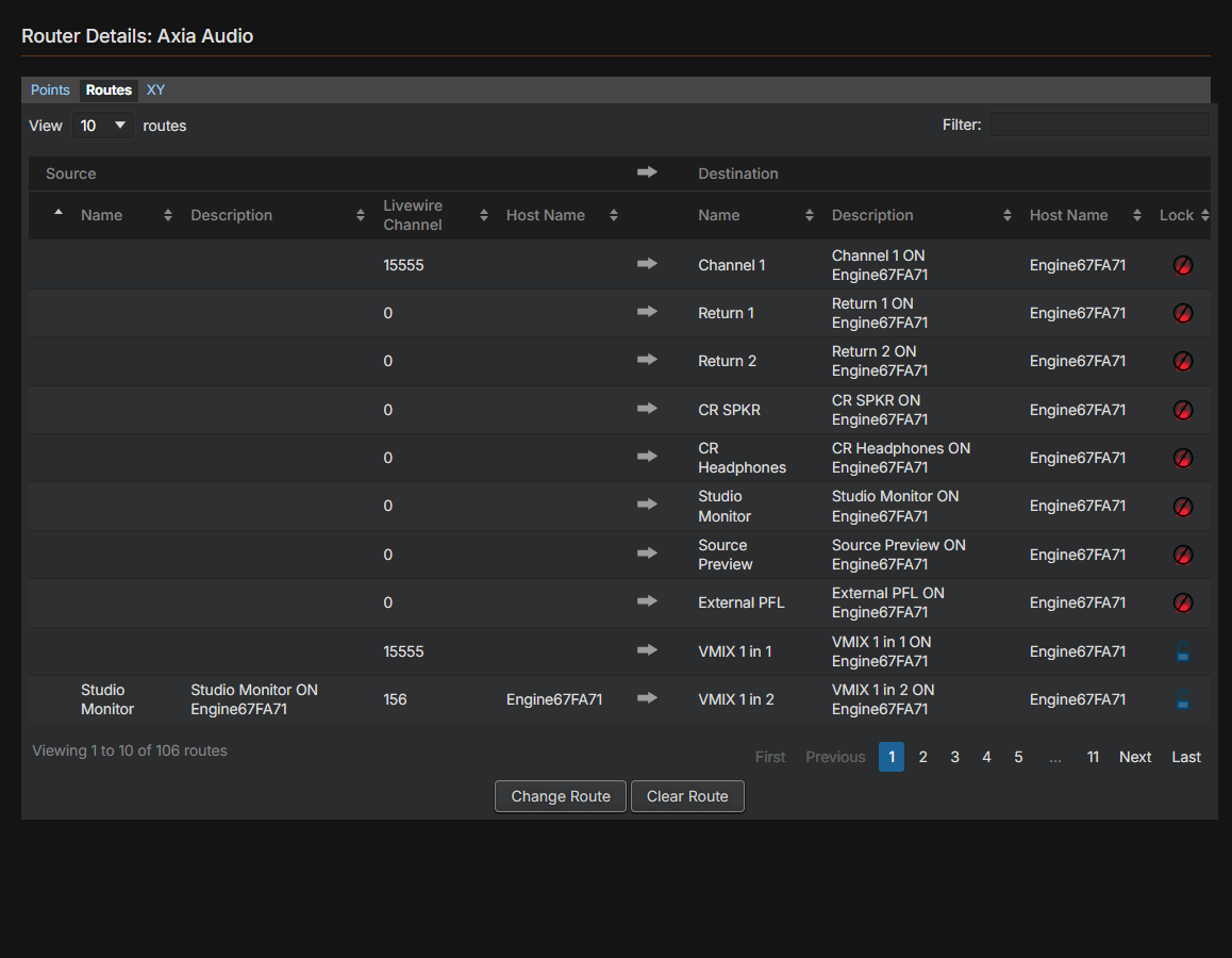
This screen has three tabs at the top: Points, Routes, and XY.
The Points Tab
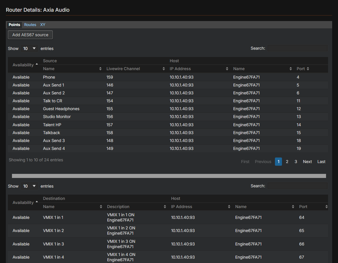
The Points tab lists sources and destinations in the router along with relevant information for each. The columns in each list are broken into two major sections:
Source/Destination: Details related directly to the source or destination, such as the source’s name, Livewire channel, and availability.
Host: Information about the host device where a source or destination resides.
Source/Destination Columns
Column | Description |
|---|---|
Availability | This column indicates whether the source or destination is currently available for use. Options include: Available—The device is operating normally Offline—The device is offline or unreachable SystemLocked—Destinations whose source cannot be changed by the router; for example, mixer faders cannot be changed using standard routing commands and must be changed using the console or by issuing special source profile load commands |
Name | The Name of the source or destination. |
Livewire Channel (Axia Audio Sources Only) | The Livewire channel number assigned to the source. |
Description (Destinations) | The description of the destination. |
Host Columns
Column | Description |
|---|---|
IP Address | The IP Address of the source or destination host device. |
Name | The name of the source or destination host device. |
Port | The physical (or virtual) port number that identifies the source or destination on the device. |
Since these lists can contain many entries, use the search box to narrow the list.
For users who have administrative rights to the router, some additional configuration tools may also be present, depending on the type of router. For example, when viewing the Axia Audio Router, a button will be present for adding AES67 sources to the router. In a virtual router, there are controls for adding virtual sources and destinations to the router. These controls are described below in the section for each router type.
The Routes Tab
The Routes tab displays the current source-to-destination routing of the router.
Again, this screen is divided into two sides. The source information for each active route is on the left, and the destination information is on the right. The columns display information about each active route:
Source Columns
Column | Description |
|---|---|
Name | The name of the source routed to this destination. |
Description | The description of the source routed to this destination. |
IO (Virtual Router Only) | The IO number of the source in the virtual router. |
Livewire Channel (Axia Audio Router Only) | The Livewire channel number of the source routed to this destination. |
HostName | The name of the device where the source resides. |
Destination Columns
Column | Description |
|---|---|
Name | The name of the destination. |
Description | The description of the destination. |
IO (Virtual Router Only) | The IO number of the destination in the virtual router. |
HostName | The name of the device where the destination resides. |
Lock | The lock state of the destination. |
Route Changes
Route changes may be made from the Routes tab by either:
Selecting an entry in the routing list and clicking Change Route
Double-clicking on an entry in the routing list
Either of these actions will present a dialog with a list of sources that may be assigned to the currently selected destination:
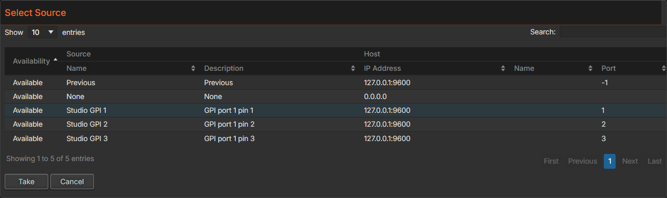
On the Select Source dialog, select the source in the source list and click Take to change the route, or double-click a source in the source list.
Click Cancel to exit the route selection dialog without making changes.
Since this list can contain many entries, use the search box to narrow the list.
The search filter can persist as you navigate between pages, so if you return to the route page and are not seeing sources or destinations that you expect to find, check whether there is a search filter on the list.
Important Note: A source will not be available in the Routes list if it is not routed to anything. It will be present in the Take list when you make a change, as well as in the Points tab under sources, but the search function only searches data that is in the list. If the source is not routed to any destination, it is not in the routes list because it is not involved in any active route.
Locking
Each route (destination) in a router can be Unlocked, Locked, or SystemLocked.
The lock state is represented by an icon in the router’s Details table:
Lock State | Icon |
|---|---|
Locked |
|
Unlocked |
|
System Locked |
|


System Locked (except for virtual routers described below) indicates that the device itself does not allow route changes to be made on that IO. This is typically seen with console faders, where source changes must be accomplished via a source profile load rather than a route change.
Important Note: Other than system locks, locking and unlocking is a Pathfinder state and does not change anything in the equipment, because Axia equipment does not have lock parameters. Therefore, a locked route in Pathfinder Core PRO could still be changed from the device’s web page.
To lock or unlock a route, click the lock icon in the route list. Locked routes must be unlocked before they can be changed. In addition, it is possible to define whether a user has permission to change route locks. When you define a security group, a field sets this permission:
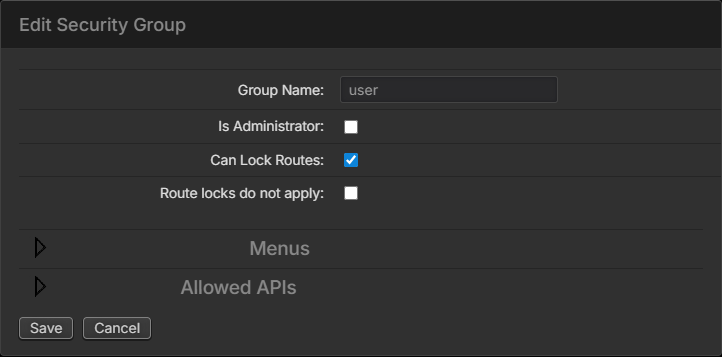
Checking the Can Lock Routes checkbox grants users in this group permission to lock and unlock routes. This allows an Administrator to lock routes and make them unchangeable by normal users.
The Route locks do not apply option allows users in this group to change routes even when they are locked.
To lock or unlock every route in a router at once, set the router's LockUserAll or UnlockUserAll property to True from a Logic Flow or over SAPv2.
Important Note: A virtual destination is made up of one or more base destinations from other routers. If you lock a virtual destination, it will not lock the underlying base destination. This is by design and allows an Administrator to create a general user router with locked destinations and an engineering router where those same destinations are unlocked. However, if the base point becomes locked, then the virtual destination will display as system locked, and the lock can only be removed by unlocking the base point. If a virtual destination has multiple base points, locking any of them makes the entire virtual destination system locked.
Unlike in previous versions of Pathfinder, locking a virtual destination does not lock its underlying base point.
The XY Tab
The XY tab presents an XY grid that lets you make route changes graphically. This tab also mirrors the functionality of the XY component available in HTML5 user panels.
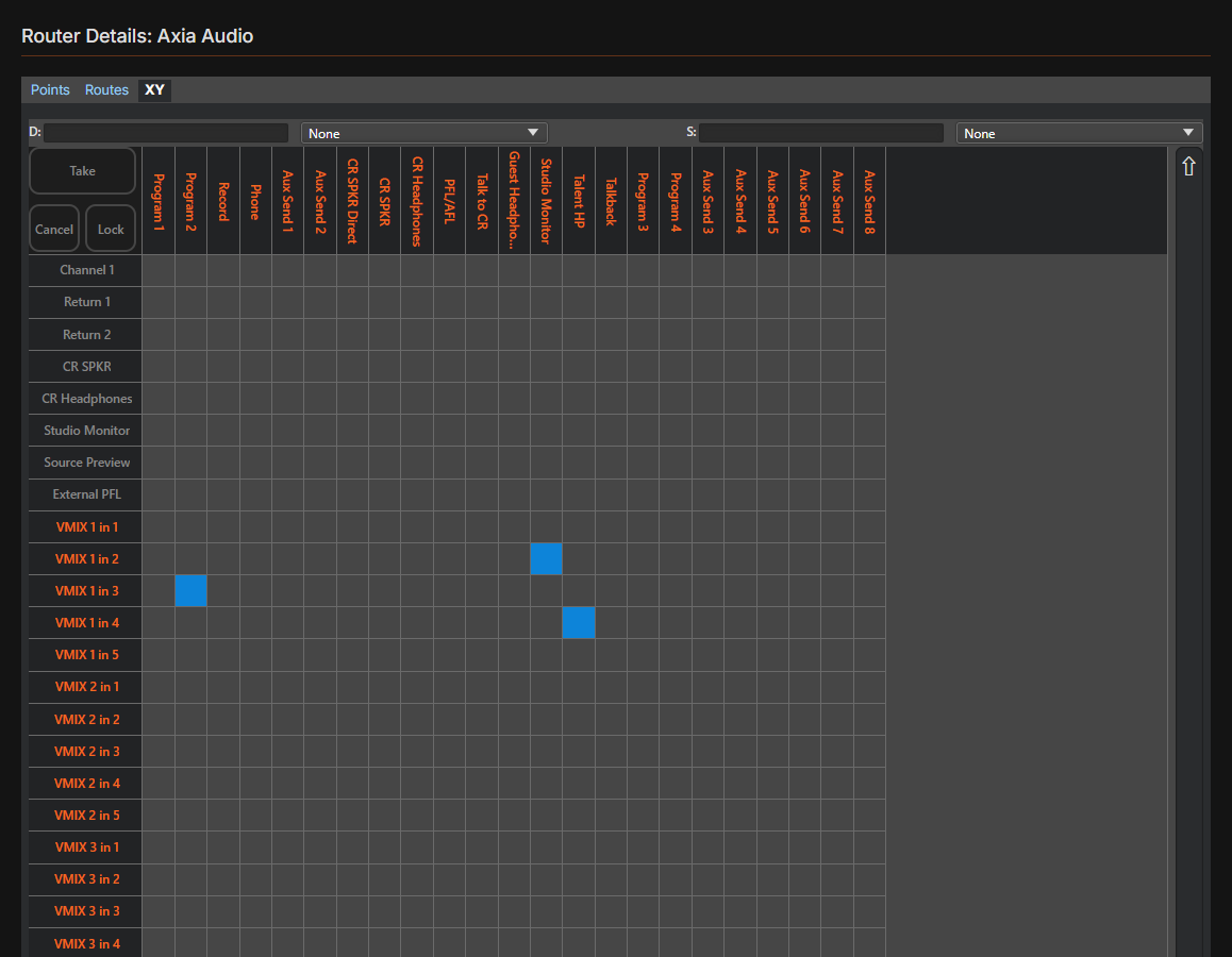
Ref | Description | Notes |
|---|---|---|
1 | Search bar | Search sources or destinations by typing in either the S or D field to reduce the number of columns and rows shown. To filter further, specify a device using the drop-down lists. The device drop-down lists are not present on virtual routers and only exist on the audio and GPIO routers. |
2 | Sources | Source Names are displayed in the columns at the top of the table. Hovering over any column header will highlight the source with an orange bar and show the source’s full description. Double-clicking a source column header repeatedly will cause the grid to jump to each destination the source is routed to and highlight it with the orange hover bars. If the source is not routed to any destination, nothing will be highlighted. |
3 | Destinations | Destination Names are displayed to the left of each row. Hovering over any row header will highlight the destination with an orange bar and show the destination’s full description. Double-clicking on a destination row header will cause the grid to jump to the source that is currently routed to that destination. If no source is routed to the destination, nothing will be highlighted. Grayed-out destination names indicate the destination is locked either at the user level or system level and cannot be changed. Double-clicking on a locked row header will still navigate to the locked cross-point if a route exists. |
4 | Scroll Bars | Scroll bars will appear if there are more destinations or sources than can be displayed. The scroll bars may be manipulated by dragging anywhere within the bar or by clicking or holding the arrows at either end of the scroll bar. The scroll bars are slightly wider than some normal Windows scroll bars because the grid is optimized for touch panel use. |
5 | Action Buttons | To take, clear, or lock a route, click the desired cross-point to preset it and then click the corresponding button in the top left corner of the grid. There are three action button sets: The Take/Clear button set will display either Take or Clear depending on whether the selected route is currently active or not. Click this button to either Take or Clear the route. The Lock/Unlock button set may be used to add or remove a user-level lock to an existing cross-point. The ability to unlock a route is restricted by user permissions. The Cancel button will clear all selected presets without making any changes. |
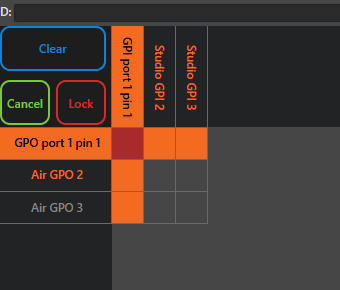
6 | Routing Grid | Clicking a cross-point will preset it and enable the action buttons. Each cross-point will have one of several colors indicating the cross-point state: gray—No route exists at that cross-point; blue—The route exists at that cross-point; system lock icon—The cross-point is locked at the system level; lock icon—The cross-point is locked at the user level; dark red—The cross-point has been preset for an action. |
7 | Preset Rotate | When a preset is selected, this button will show the count of selected presets. Clicking the button will cause the hover bars to highlight the selection and move the scroll bars to the correct preset cross-point. If the matrix has been configured in multiple preset mode, this button will loop through the currently selected presets. The button will be grayed out and unavailable for use when no presets have been selected. |
Clicking an empty cross-point presets it (dark red) and lights Take and Cancel:
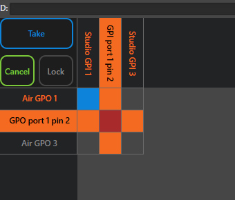
Clicking a cross-point where a route already exists (blue) changes Take to Clear and lights Lock, so the route can be cleared or its destination locked:
Execution Blocks
When a router is stopped by an execution block (see the Block Execution article), it is shown in red in the routers list, and its Routes and XY tabs show a warning. Route changes are not made until the block is removed.
Router Types
Axia Audio Router
The Axia Audio Router is created automatically by the system. As devices are discovered or manually added to the system, they are analyzed to determine what audio sources and destinations they provide, and those sources and destinations are automatically loaded into this router.
When you use this router to make a route change, Pathfinder Core PRO contacts the destination device and sends it a command to change the source assigned to that destination. This is much the same as making the change from the device’s web page, except that with Pathfinder Core PRO you can see all of the audio IOs in one place. Pathfinder Core PRO can also execute scene changes that make hundreds of route changes across many devices at once.
In the Points tab, some sources have an IP address of 255.255.255.255:93, have nothing in the host name column, and have “To:” at the start of their Name.
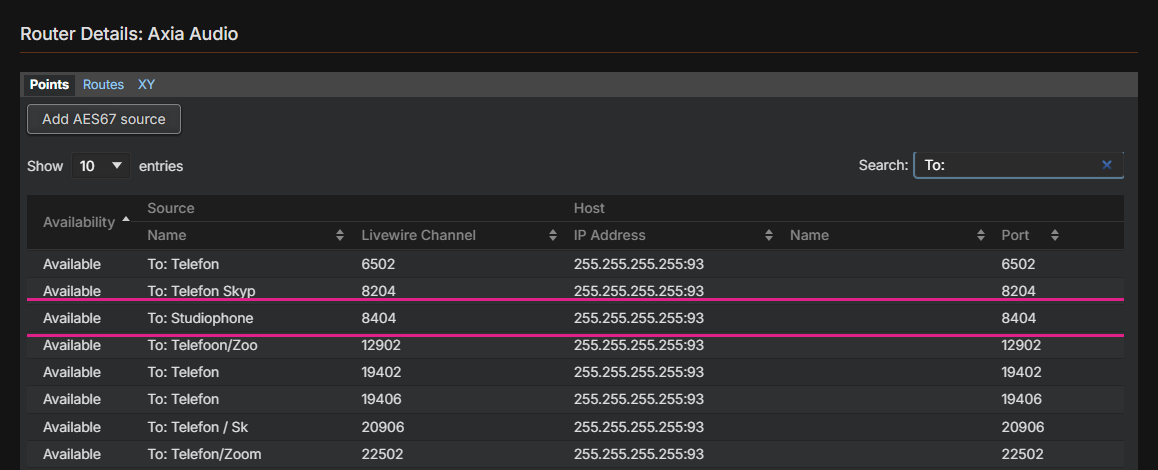
These sources are Axia Backfeeds generated by the mixing engines. They are not assigned a specific host because they are the only type of source that can dynamically change which device (Engine) is currently hosting them, so they have no fixed host. To learn more about Axia Backfeeds, see any of the Axia Mixing Console manuals.
The Points tab of an Axia Audio Router also has an Add AES67 Source button. Click this button to open a dialog for adding AES67 sources to the system.
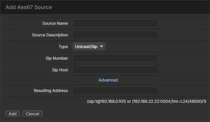
Type the name and description by which the source will be identified in the system in the Source Name and Description fields. The AES67 specification allows for sources to be defined using a Unicast/Sip or multicast address format. The information required to define the source depends on the selected format, so the fields change with the format you select. The example above shows the unicast method. Enter the number and the host IP address required to define the Sip path. The resulting address field will automatically fill with the address required for this source based on these parameters.
If you select the multicast option, the required fields will change:
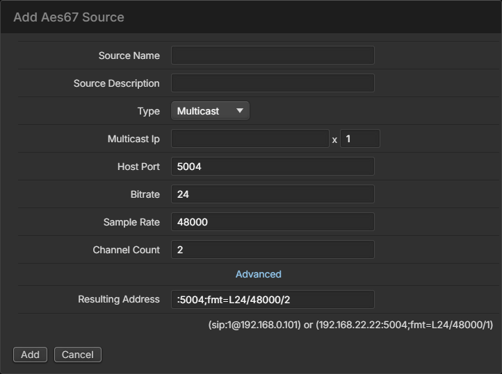
In this case, fill in the multicast IP address and adjust the other parameters to reflect the AES67 source settings, then click add to add the source.
To add a range of multicast AES67 addresses instead of adding them one at a time, use the second field beside the Multicast IP field, which sets the number of IOs to add. By default, x1 is selected, which adds only one new source. Changing the x parameter to a larger number (say 255) loops through that many IOs, incrementing the multicast IP and adding an underscore and number to the source name, and adds them to the router.
Once added, AES67 sources have a trash icon in the list of points for deleting the source and an edit link that returns to the editing dialog shown above.
Once these sources are added to the router, Pathfinder Core PRO can instruct any Axia device destination that supports AES67 streams to receive a specific AES67 stream in the same way as normal Axia route changes are made.
Several Axia Audio Routers
Large systems can split their audio sources and destinations between several Axia Audio routers by IP address range. This is turned off by default; to turn it on, add SET Routers#0 EnableAutoInsertLimitsUI=True in System > Configuration > Advanced Options. Add + on the Routers page then offers Axia Audio Router with an IP Range, and each audio router gets an Advanced link with its Auto Insert Limits. Devices whose addresses fall in a router's range are added to that router. The first audio router cannot be deleted.
Axia GPIO Router
The Axia GPIO Router is very similar to the Axia Audio Router. As devices that have GPIO ports are discovered, those ports are added to this router. As with the Axia Audio Router, when you make route changes, Pathfinder Core PRO sends the destination node a command that tells a specific GPO on that device to follow the GPIs of the selected source device and port. Because of how GPIOs work on an Axia network, this routing needs some explanation.
There are three ways to route GPIO closures across an Axia network. The Axia GPIO Router in Pathfinder Core PRO only uses one of these methods. It is still important to understand all three, because using conflicting methods at the same time on a GPIO port can cause erroneous and unpredictable closures.
First, within the Axia device itself, you can assign a channel number to a GPIO port. This tells the port to bind itself to Axia Mixing Console GPIO signals from whatever console currently has that Livewire channel number loaded.
Second, you can assign an IP address and port number of a GPI to a GPO. This is called "snake mode," and it is what the GPIO Router uses to tell a device’s GPOs to mirror another port’s GPIs. Therefore, when you make a route change in the Pathfinder Axia GPIO Router from Node 1 Port 1 to Node 2 Port 4, any GPI closures on Node 1 Port 1 will be mirrored as GPOs in Node 2 Port 4. These route changes can also be updated dynamically, just as with any other router.
The third way that GPIOs can be used is to leave both the Livewire channel number and the routing assignment unassigned, then directly trip the closures using Pathfinder’s (or some other automation system’s) event system by sending closure commands to the device.
These three methods matter because you can use more than one of them at the same time, which is occasionally useful but more often a mistake. For example, we often see users who think that the GPIO ports should have a Livewire channel number and so assign one arbitrarily. This can lead to a situation where the user has created Pathfinder events to make and respond to changes on those ports, but those same ports are also being fired by changes on the mixing console, which causes confusion and generates calls to Telos Support. First decide how you intend to use a given GPIO port, then configure it correctly for that task.
Imagine Logical Router
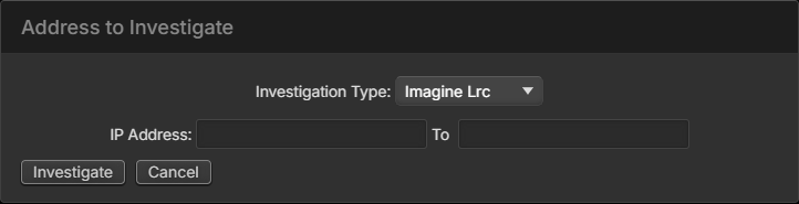
To add an Imagine Router into Pathfinder Core PRO, you must first add the Imagine Device to the Devices list. In Devices, click Add +, type the IP Address, and select Imagine Lrc from the Investigation Type drop-down list, then click Investigate.
Once the device has been successfully added, click the Routers link and click Add +.
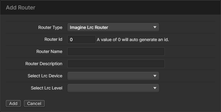
Field | Description |
|---|---|
Router Type | Select Imagine Lrc. |
Router Id | Id number of the router. Leave a value of 0 for an auto-generated Id. |
Router Name | Type a descriptive name for this Router. |
Router Description | Optionally, type a description for this Router. |
Select Lrc Device | From the drop-down list, select the specific device. |
Select Lrc Level | Select the LRC level in the router to control as described below. |
Imagine routers have multiple levels and Pathfinder Core PRO can control full routes that route all levels at once by adding the level. Any given breakaway level may also be added separately. Or, both may be added in different routers. This allows routes that should target all levels to be made on the router with the All target and routes of individual breakaway levels to be made on the breakaway routers.
Once added, the router will discover the IOs made available by the selected level and routes may be manipulated in the same way as other routers in the system.
Virtual Routers
Virtual routers are a special kind of router. You can think of a virtual router as a way to make a subset of routes you wish a specific user to use. For example, you could create a router that only contains the routes from the Axia Audio Router that are related to a specific studio. Or you could create a router that only contains the routes that are relevant to the final air chains. This allows you to create purpose-driven routers that display only the routes that are relevant to a specific set of tasks and are therefore much easier to navigate than browsing every source and destination on the network.
However, virtual routers can also go much deeper than just subsets of routes. For any specific virtual source or destination, you can also associate multiple real sources or destinations with that virtual source. That sounds complicated, but it is relatively simple and very useful.
For example, let’s say that every time you route a specific Audio Source to a specific Audio Destination, you also want to route a GPIO source that carries signaling information related to that audio source to a specific GPIO destination. An example of where this might be useful would be switching from a primary automation system to a backup automation system by creating a virtual source that contains both an audio and a GPIO source plus a virtual destination that contains both an audio and a GPIO destination. Now, when you use the virtual router to route that source to the destination, it will tell the underlying audio and GPIO routers to make both routes.
To create a virtual router, click Add + on the main routers page and choose Virtual Router.
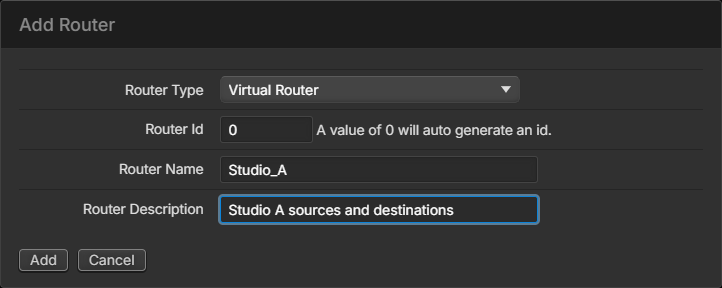
Provide a name and description for the router and click Add. The router id defaults to the next available id number, but you can enter your own. Be sure to use a unique id that is not already in use by another router.
After you click Add, the virtual router appears in the routers list, but it is empty because it has no sources or destinations yet. Click the Details link and select the Points tab.
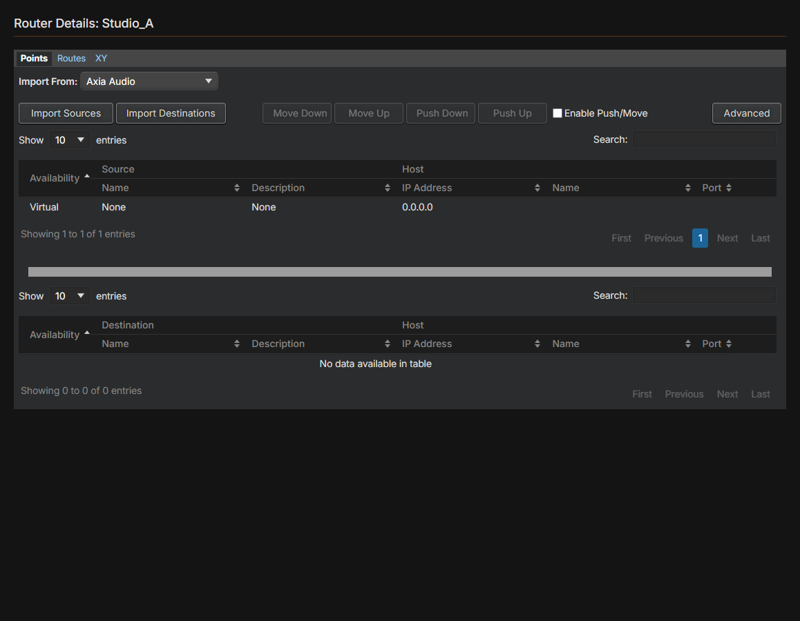
The easiest way to populate a virtual router is to import some sources and destinations from a real router. In this example, select the Axia Audio Router from the import drop-down and then click Import Sources. A list of importable sources appears.
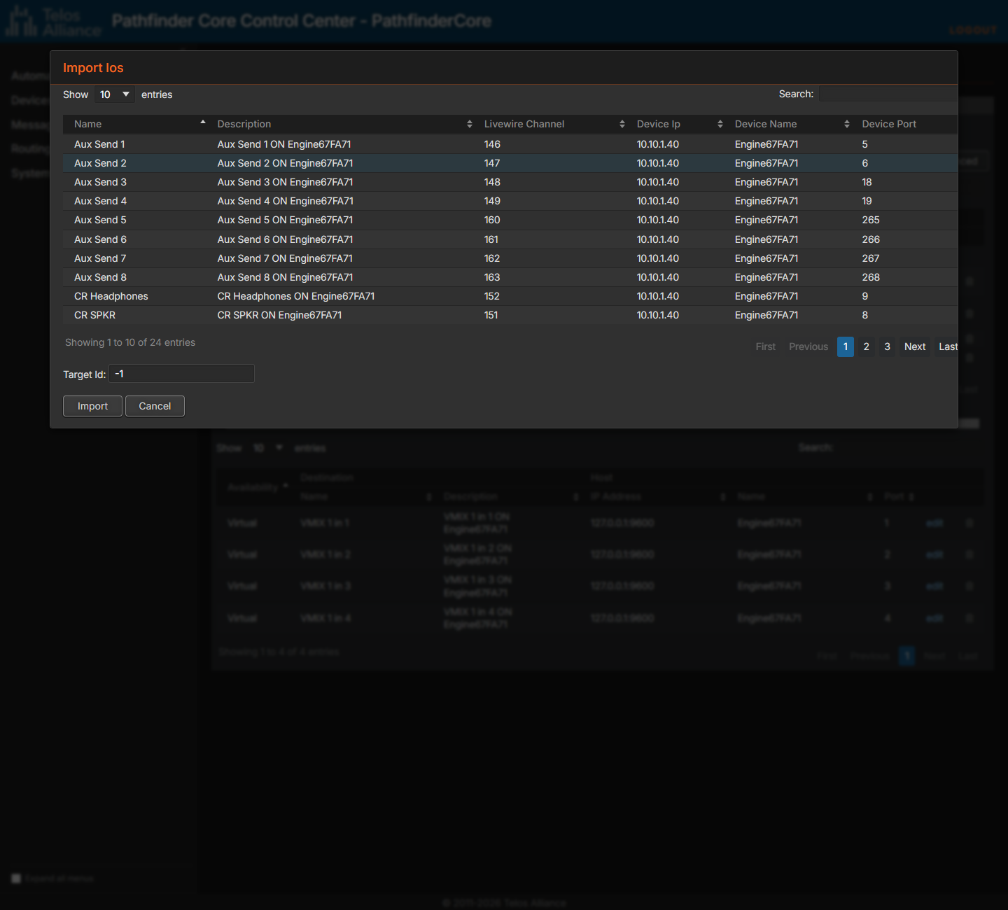
Click the sources you want to import (Shift-click to select a range), then click the Import button. Repeat the procedure with the Import Destinations button to import additional destinations into the virtual router. In general, leave the target id at -1. This will import the IOs to the end of the router. Setting a number other than -1 will try to import the new IOs at the number selected. This will fail if there are not enough open numbers at the target id to support the number of selected IOs.
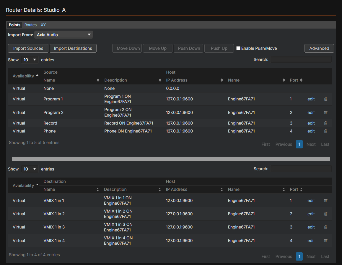
At this point, you have a virtual router with only the sources and destinations you want available. This router can then be made available as the only router certain users have access to by using the user rights section, or it can be used to easily see and change certain critical routes without viewing the entire Audio router.
However, let’s dig a little deeper into each individual virtual IO. If you click the edit link on one of the imported virtual sources, you will see more details about the virtual source.
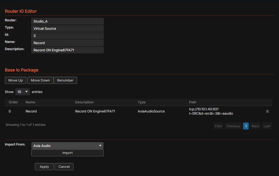
By default, when you import a source, the name and description fields of the virtual source inherit the name of the imported source. You can change these to anything you want in the name and description fields. The Base Io Package allows you to define which real sources are a part of this virtual source. As mentioned earlier, it is possible to tie multiple sources together into a single virtual source package. For example, we could select the GPIO router from the Import From dialog, click Import, then select a GPIO source to include in this package.
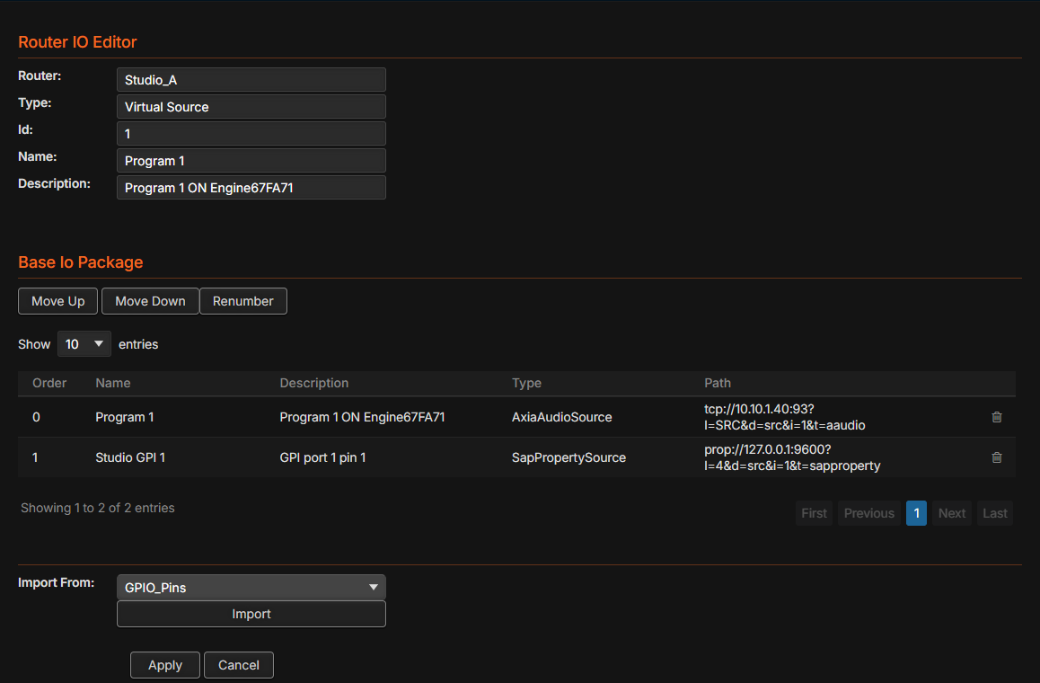
The Move Up, Move Down, and Renumber buttons allow you to change the order of the sources in the virtual source package. Once applied, this virtual source now has both a GPIO and an audio source, so routing it to a virtual destination attempts to make both a GPIO and an audio route change underneath. The same process can be used to edit and manipulate the virtual destinations.
The Points tab on the virtual router also includes an Add + button for manually adding virtual sources and destinations and a trash icon for deleting a virtual source or destination from the router.
Deeper Tech: Packaging
This section explains what happens under the hood with virtual routers. Every virtual source or destination is a package. Within that package is a list of pointers to real sources or destinations. When you make a route change, the system does a number of things.
First, it attempts to organize the package according to the IO types of the pointers in both the source and destination package. For example, it will group all of the GPIO points together and all of the Audio points together in each package. Then it will try to make one-to-one routes based on the order of the routes in the package.
This also allows you to group multiple Audio sources and destinations into a single package. For example, if you were using some sort of immersive sound configuration that required multiple channels of audio (7.1, 22.2) to be routed at once, you could package all of the sources together into a virtual source package and all of the destinations together into a virtual destination package. When the virtual route is made, Pathfinder Core PRO will step through each line in the source package and try to apply it to the same line in the destination package in the order in which they exist in the package. If the count in the source and destination packages does not match, the system will go as far as it can to create the matches. For example, if the source package has 1 source and the destination package has 2 destinations, only the first destination will get a route. If the source package has 2 sources and the destination package has only a single destination, only the first source is applied.
In the same fashion, the state of virtual routes is updated automatically as base routes in the packages change. If an audio route changes and the source and/or destination exists in a virtual router, an analysis is done to determine if the current route states of any of the source packages match what would happen if the source were applied to the destination. If they do, the virtual route is updated to reflect that source as the current route. If multiple source packages match the destination, then the first one with the most matches is displayed as the currently routed source.
If no source package matches a destination package, the route may have two other states. The first is “None”, which means that none of the destination package's destinations are assigned to anything. The other state is “Other”, which means that some of the destination package’s destinations have some route applied to them, but it does not match any of the source packages in the virtual router. This distinguishes a cleared destination from one that is in use in a way the virtual router cannot represent with its current configuration.
IO Ordering – Move Up/Down and Push Up/Down

The virtual router page also has a block of controls used for manipulating the order of the IOs in the router. These controls are only available to Administrative users. These buttons effectively alter the number of the IO in the virtual router. Since changing the IO numbering of a virtual router can have deeper consequences if the IOs are already in use by Logic Flows or device emulators, you must select the Enable Push/Move checkbox to enable these buttons, which prevents accidental changes.
Sort by Port when using this feature, because it moves IOs up and down by port number, not by sort order. This is a design tool to create specific numbering for the virtual IOs and is most useful when those IOs will be exposed to emulated routing protocols that expect a number to be assigned to each IO.
Move Up – moves the IO up in the router, effectively decreasing its IO number and swapping with its lower next-door neighbor if necessary.
Move Down – moves the IO down in the router, effectively increasing its IO number and swapping with its higher next-door neighbor if necessary.
Push Up – moves the IO up in the router, effectively decreasing its IO number and pushing any lower-numbered IOs it runs into up as well, decreasing their numbers until it reaches a hole in the numbering or 0.
Push Down – moves the IO down in the router, effectively increasing its IO number and pushing any higher-numbered IOs it runs into down as well, increasing their numbers until it reaches a hole in the numbering or the highest value in the router.
Advanced Base IOs and the Enable Property
Each virtual source and destination’s base points in a virtual router also include an enable property which can be true or false. This can be used to disable the base point from being considered during route changes and route state analysis. This property is only available via the API tree in Logic Flows as it is considered an advanced property.
Here is an example of where this feature might be useful: Let’s say we are mixing audio for an air chain using a vmixer. We might create a virtual router with the virtual mixer destinations and the possible studio sources. However, what if for redundancy's sake we wanted to duplicate the settings of a vmixer on a second engine, so that we could feed the air chain from either engine and take one or the other out of service? To accomplish this, we could create a virtual router with destination base points using vmixer channels from both engines and where the source points are the same source base point duplicated.
In the API tree, each base point of a virtual source or destination appears as VirtualBaseIo#n, with its Enabled property beside its Path and the two override options described below:
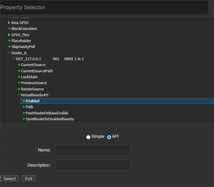
If this virtual source were routed to the virtual destination, the same base source would get routed to the vmix destination on both engines, and the route would only show active if it was successfully made on both engines. However, if we wanted to take engine number 2 offline for maintenance, our route changes would still be sent to both engines, but the state would not be displayed since the offline engine did not show the successful route.
Using the enable property of the base points, we could create a scene or a Logic Flow that disabled the destination base points for the second engine while it is in maintenance. The virtual router would continue to work as if those base points did not exist in the destination. Then we could execute a second scene when the engine comes back online to re-enable those base points.
Each virtual router also has write-only properties for enabling or disabling many base points at once: DisableBaseIoByPathContains and EnableBaseIoByPathContains act on every base point whose path contains the text you send (for example an engine's IP address), and the …BaseSrc… and …BaseDst… versions act on sources or destinations only. Sending 10.10.1.40 to DisableBaseDstByPathContains would take every destination base point on that engine out of service in one step.
Advanced: Push Route on Base Io Enable
This feature works with the base Io enable/disable feature above. On the Points tab of a virtual router, there is an Advanced button on the far right side. Clicking the Advanced button will open a dialog for advanced options.
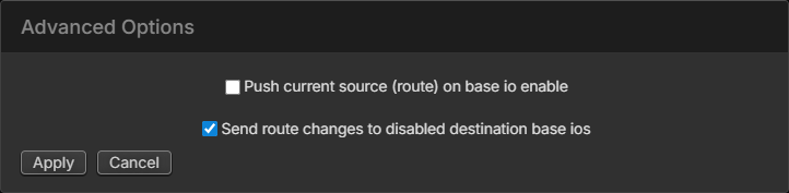
This option defines what happens when a virtual source or destination’s base point was set to enabled=false and changes to enabled=true. If the option is checked, then the existing route state is re-applied to update the state of the base point that was just re-enabled with the current source. If this option is not enabled, no change will be made when the base point is enabled. That is, the route state may change to something like Other since the newly enabled base point does not fit the current source-to-destination pairing.
By default, if a base IO within a virtual router destination package is disabled, route changes are still sent to that base IO if the virtual destination's source is changed. This is intentional. There may be times when you want to fix the base IO destination to a source and ignore other route change requests to it. In this case, disabling the base IO and turning the "Send route changes to disabled destination base ios" option off may be appropriate. In that case, when a new virtual source package is applied to the destination, base IO sources that would normally be applied to that disabled base destination will be skipped. Then, when the destination base IO is re-enabled, the current source base IOs will either be sent or left in their current state depending on the Push current source (route) on base io enabled option.
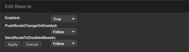
These two options also exist on each virtual router's destination base IO. By default, the parameters on each base IO are set to Follow, which means they use the overall route advanced settings. But they can be overridden to create different behavior on individual base IOs. Do this either from Logic Flows or with the edit link when editing a virtual destination. Clicking the link will open a dialog where these options can be overridden. The dialog also presents an option for toggling the base IO disabled state via the UI. To override the router advanced option, change either of the two options from Follow to the enabled or disabled setting you want. Remember, these settings only affect the functionality when the base IO is disabled or returning from disabled to enabled.
Sap Property Router
With the Sap Property Router type, any property that can be read in Pathfinder Core PRO can become a router source, and any property that can be written to can become a router destination.
For example, in the legacy Pathfinder Pro, it was possible to create a router of individual GPIO pins instead of routing entire ports using the GPIOByPin router. This same functionality can be realized with a Sap Property Router in Pathfinder Core PRO.
Creating a Sap Property Router
To create a Sap Property Router, browse to the Routers navigation link and click Add + to create a new router.
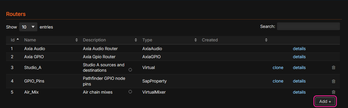
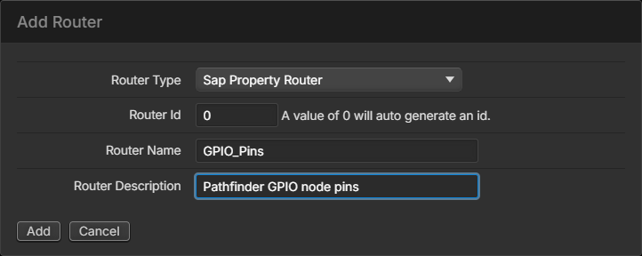
Select the Sap Property Router from the drop-down list of available Router Types. Click Add to create the new router.
Adding IOs
To add IOs to your new router, click the Details link and then click the Points tab.
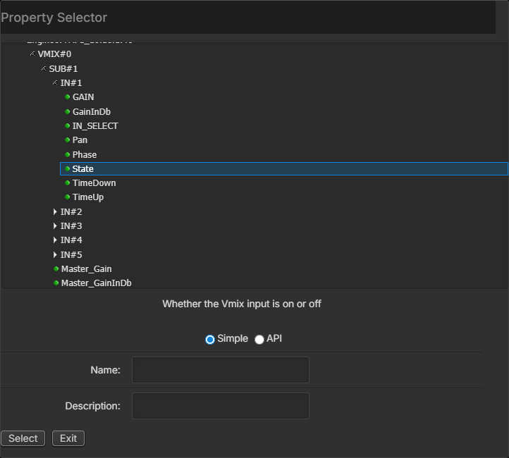
As with the virtual router, you will see Import Sources and Import Destinations buttons as well as a Translation button. However, clicking these buttons for this router will display the property selector used in Logic Flows.
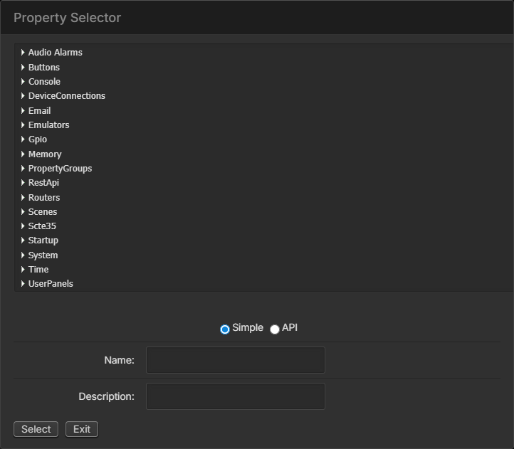
In the example above, we select a GPI PinState property.
Type a name and description for the IO (or use the default) and click Select. Repeat for other pins you want as sources, then import the destinations.
A source or destination can also be a whole object instead of one property. Select the object (arrow icon) in the property selector rather than a property (green dot icon), and click Continue in the Select Object message. The router then passes the properties of the object, and of the objects below it, from the source to the destination, in the same way as an Object Translator in Logic Flows. Use objects of the same kind for the sources and the destinations.
If the ports you are using for destinations are on a Livewire driver or Pathfinder Core PRO GPIO node, you can use GPI pins as the destination and route GPI to GPI. When you are done, it might look something like this:
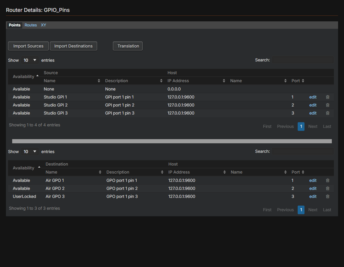
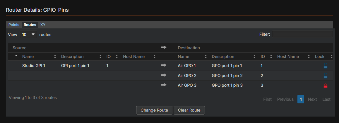
If you go to the Routes tab, you will see the destinations with a "take table" of the sources where you can make route changes.
In this example, Studio GPI 1 has been routed to Air GPO 1. Therefore, any closures that take place on Studio GPI 1 will be replicated on Air GPO 1.
Translation Patterns
Clicking the Translation button on the Points tab will open the translation pattern used for any values that pass from the source property to the routed destination properties. This is a single translation pattern that is used between the source values and destination values.
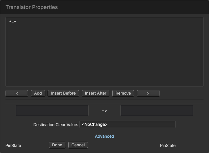
In the example above, the translation pattern is *=*. Using this pattern, a pin low on the source side will cause a pin low on all destinations to which the source is routed. If you change this translation to l=h and h=l, lows on the source generate highs on any destination to which that source is routed.
The dialog also holds the Destination Clear Value, the value sent to a destination when its route is cleared (see Destination Clear Value below). Click Advanced for more settings:
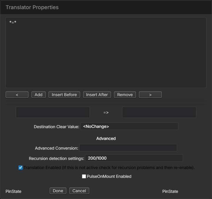
Advanced Conversion: an advanced conversion applied to the values, as in Logic Flow translators.
Recursion detection settings: how many changes in how many milliseconds (by default 200/1000) are treated as a loop. When a loop is detected, translation is turned off.
Translation Enabled: turn this off to stop values from passing through the router. If it has turned itself off, look for the loop before turning it on again.
PulseOnMount Enabled: when the system starts, once startup is complete and the router's IOs are available, the current value of every source is sent through the router, so the destinations match their sources immediately. The pulse waits until every source and destination in the router is available. If one of them points to an object that no longer exists, the startup pulse does not run, so remove that IO from the router. The router's read-only
AllIosMountCompleteproperty shows whether every IO is available.
To send every source's current value through the router at any other time, set the router's PulseAllSources property to True from a Logic Flow or over SAPv2.
Sap Property and Virtual routers also have an ExecutePattern property, which makes several routes at once: ClearAll clears every destination, LeftToRight routes source 1 to destination 1, source 2 to destination 2 and so on, OneToAll routes source 1 to every destination, and LastToAll routes the highest-numbered source to every destination.
Translation patterns may be applied to other properties. Applying a translation pattern of l=5000 to the Pulse state would force the output to go low for 5000ms each time the input went low. With no h= value defined, nothing would happen when the input went high.
While we could achieve these results with Logic Flows, configuring a router allows the start point of a flow to change dynamically. For example, suppose we have a Vmixer assigned to each air chain with channel 1 representing the feed from the studio console. There is a GPI pin in the studio which turns the Vmix channel on. This is simple to accomplish with a Logic Flow:
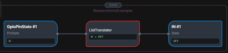
What if we have 5 studios and any one of them could be assigned to the air chain? Using Logic Flows, this becomes much more complex because we must build flows for each studio-to-air-chain variation. However, this becomes easy with a property router. On the source side of the router we select the GpiPinState property, and on the destination side we select all air chain Vmix IN state properties:
Once the items are selected, we can change the translation to l=ON and h=OFF.
Now when we route a studio pin to the air chain Vmix, the low from the studio will control the Vmix state of whichever air chain that studio happens to be routed to.
We can extend this example by using a virtual router where the virtual source package includes the audio console program bus audio source and the pin source from the Sap Property router, and the destination package includes the Vmix channel input audio destination and the Vmix state property from the property router.
These signals are tied together so that a single virtual route change switches both audio and signaling. That virtual router can then be controlled by a third-party application using something like Probel without that application needing to know that we are actually switching numerous things under the hood. This makes many new kinds of routing possible.
Another interesting example uses many of the new features described above. What if we wanted to route a TCP stream of song data to different destinations depending on what is currently on the air? We could create generic device emulators for each destination and each song data source. Using the regex capability, we could then add a watcher to the emulators on the source side that looks like:
Regex.Match((?s).*)
This will match any data coming in. Then, we create a new property router and choose the watcher TranslationValues for the sources. For the destinations, we select the ToSend property of the destination generic emulators. This will essentially pass any data that comes into the source emulator to the output of destinations to which that source is routed. Then we could also add those points to the air chain virtual router so that audio, studio pin to Vmix state, and song data are all tied together as a single virtual route.
Another possibility might be to route memory slots. Or, we could use the duration regex example above to capture different satellite duration data as source points in a router that then gets passed on to countdown clocks.
The point is, you can now route anything Pathfinder knows about.
In each example above, all sources and destinations in a given property router are of the same type. While this is not strictly required, it is usually good practice. Once you start mixing IO property types in the same router’s sources or destinations, the translation table can become non-intuitive and it is possible to output the wrong data to devices.
Because there is no route state in the equipment for this type of routing, to retain the route state between restarts, this router must store all route changes (not the values transitioning through the routes) to the backing storage. On the fanless engine, which uses compact flash for this storage, we have implemented some protections to reduce the write cycles. Still, avoid recursive millisecond route changes on Property routers where you can, for example a rotation circuit that continuously loops through changing property routes. This is less of a concern with the R2 platform, which uses SSD, and with the VM version.
Destination Clear Value
When a destination's route is cleared, the destination has no source, so by default nothing is sent and the destination keeps the last value it received. The Destination Clear Value in the router's Translation dialog sends a value instead, so the destination goes to a known state. For example, with a clear value of h on the router above, clearing Air GPO 1 releases that pin even if Studio GPI 1 was low when the route was cleared.
A route is cleared when its destination is set to None: from the Routes tab, with Clear on the XY tab, by routing source 0 from a Logic Flow or SAPv2, or with the ClearAll pattern of ExecutePattern (described above).
<NoChange> (the default) sends nothing.
Any other text is sent to the destination property exactly as typed. The translation pattern and any destination delay are not applied, so enter a value the destination property accepts, for example
horlfor a GPIO pin.An empty field is not the same as <NoChange>: it sends an empty value.
Each destination can also have its own clear value. On the Points tab, click edit beside the destination and then Translation:
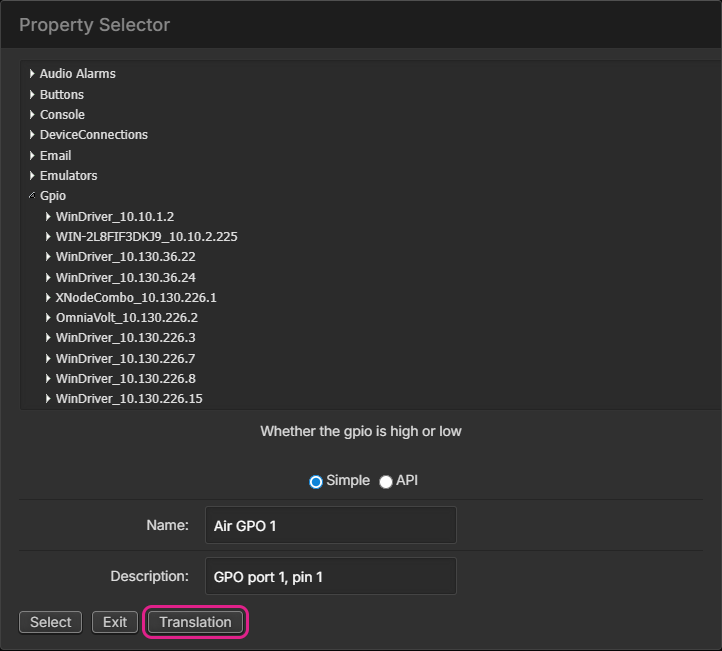
The destination's dialog shows Destination Clear Value and Destination Delay in ms. <DefinedByRouter>, the default for new destinations, uses the router's clear value; any other entry, including <NoChange>, applies to that destination only. Sources have no clear value.
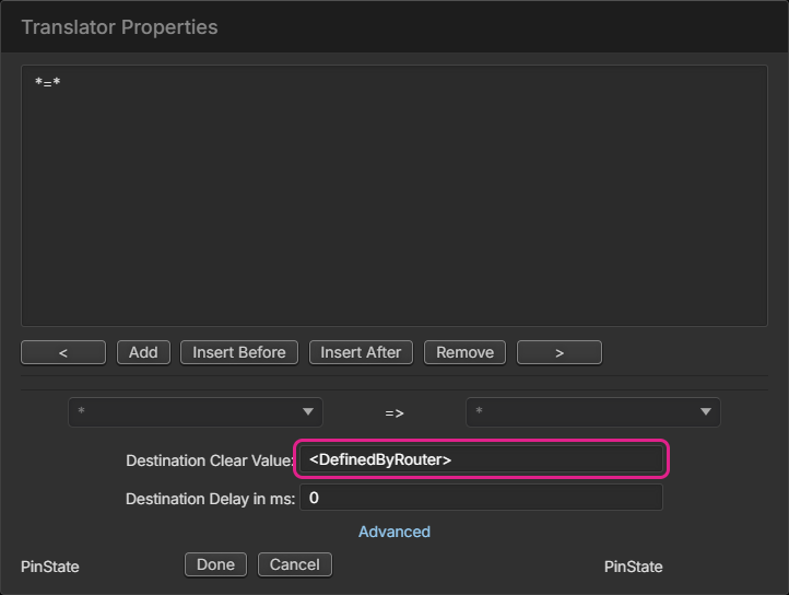
If you change a destination's own clear value while that destination is cleared, the new value is sent immediately. A change to the router's clear value, or to the clear value of a whole-object destination (below), is sent the next time a route is cleared.
When a destination is a whole object rather than one of its properties, the clear value names the properties to set, as Property=Value. To set several properties, separate them with the text \cr\lf, for example PropertyA=Value1\cr\lfPropertyB=Value2. To set a property of an object below the destination, start the entry with that object, for example Child#1 Property=Value. For a memory slot destination, a value on its own, such as NONE, sets the slot's value.
Virtual Mixing Router
The virtual mixing router can be used to dynamically add and remove sources from a destination that accepts multiple sources, such as a vmixer. Its usage will become clearer as we work through an example. To create a virtual mixing router, browse to the routers page and click Add + to add the router. From the Router Type, select Virtual Mixing Router, provide a name and description, and click Add.
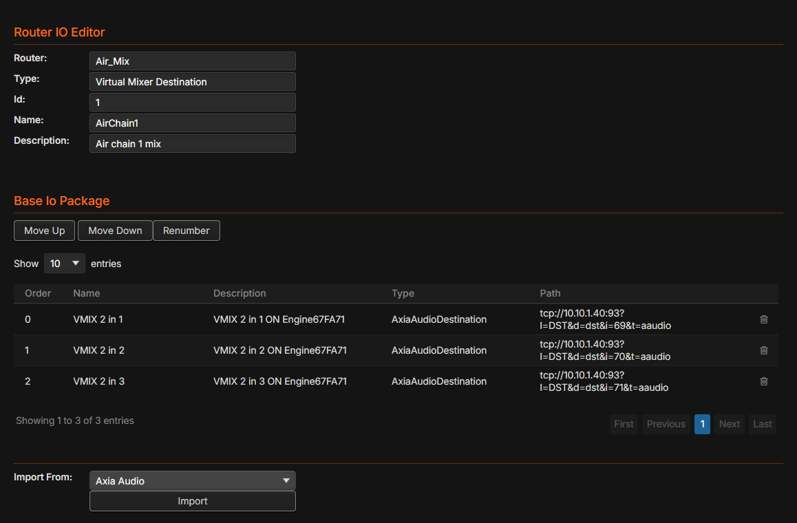
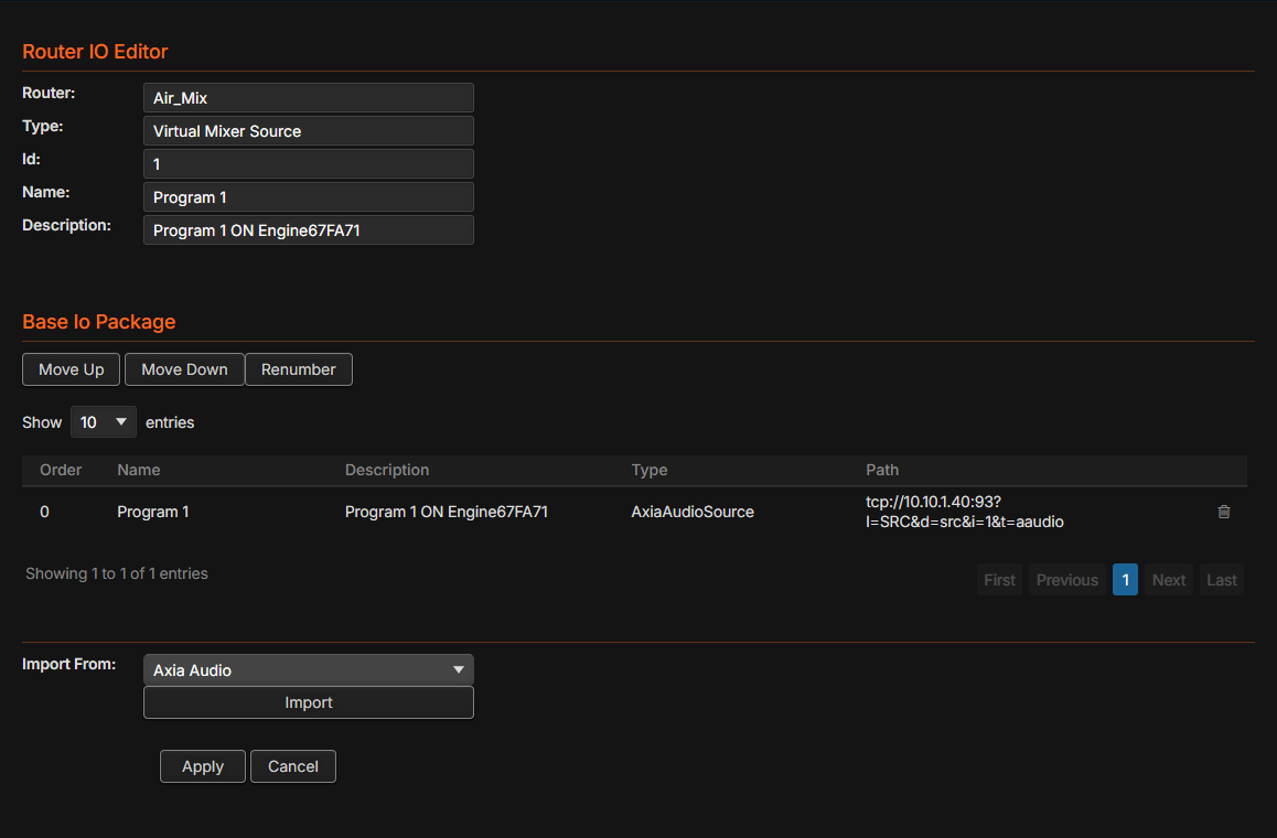
The virtual mixing router is created and populated in the same way as a virtual router, but it behaves differently. A virtual mixing router only allows a single base point for each source and assumes that the base points of a destination mix together. Therefore, you can apply multiple sources to the same destination up to the number of base points you have defined for the destination. For example, say you have 10 studios and 4 air chains. However, some of these studios are newsrooms which may need to be mixed in with the main studio. In this case you can use a vmixer on an engine to mix these together. We could then use the Virtual Mixing Router to dynamically route studios into the vmixer. To do this we would create the virtual mixing router like this:
Destination:
Source:
If we added additional sources and destinations where the destinations were made up of multiple mixed (vmix) destinations and the source was a single source, we would end up with a router that can look like this:
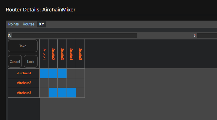
The destination AirChain1 has three sources assigned to it, and because the destination’s base points are in the same vmixer, these are mixed together. Pathfinder Core PRO does not do any audio mixing. No audio passes through Pathfinder Core PRO. Rather, you are telling Pathfinder Core PRO that these destinations are all part of a mixer.
Routing a source to a destination in a Virtual Mixing Router works differently than in a normal router. In a normal router we assign a source to a destination using the CurrentSource or CurrentSourcePath property. With a Virtual Mixing Router we use a different set of properties called AddSource, RemoveSource, and SwapSource.
When you apply a source number to a virtual mixing destination’s AddSource property, the system will review the destination’s base points. If the source is already assigned to one of the destination’s base points, then no change is made. If it is not assigned and all of the base points already have a source assigned to them, then no change is made. If it is not assigned and one of the destination’s base points is cleared, then the source will be applied to that base point. Therefore, you can route as many sources to the destination as the destination has base points and they will be dynamically used.
Conversely, when a source number is applied to a destination’s RemoveSource property, the system will check to see if that source is applied to any of the destination’s base points, and if so it will clear that base point.
The SwapSource property checks whether a source is applied to one of the destination’s base points. If not, it attempts the same actions as AddSource. If it is applied, then it executes a remove source. This is useful for toggle buttons that add and remove sources from a destination.
While this router’s sources can only have a single base point, it is possible to combine points by putting the base points in a virtual router and then targeting the virtual router as the base points of a virtual mixing router.